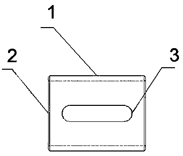
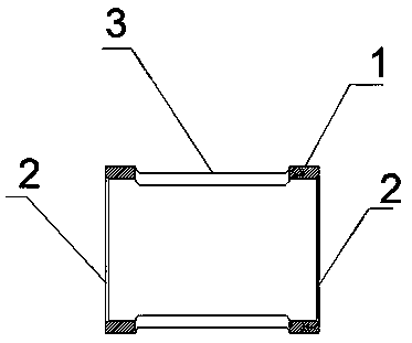
Lock sleeve

A lock sleeve and lock body technology, applied in the field of lock sleeves, can solve problems such as difficulty in breaking and dismantling door locks, damage to door panels, etc., and achieve the effects of simple structure, reduced production cost, and easy processing and production.

Inactive Publication Date: 2019-05-17
重庆市江津区长江机具制造有限责任公司
View PDF0 Cites 0 Cited by
  • Summary
  • Abstract
  • Description
  • Claims
  • Application Information

AI Technical Summary

Problems solved by technology

At present, most of the door locks on the door are pre-embedded installation structures. The door lock sleeves are all buried in the door panel, and the front end of the door lock is flush with the surface of the doo

Method used


Image

  • Lock sleeve
  • Lock sleeve

Examples


Embodiment Construction

[0013] The technical solutions in the embodiments of the present invention will be clearly and completely described below in conjunction with the accompanying drawings in the embodiments of the present invention. Obviously, the described embodiments are only some of the embodiments of the present invention, not all of them. Based on The embodiments of the present invention and all other embodiments obtained by persons of ordinary skill in the art without making creative efforts belong to the protection scope of the present invention.

[0014] In describing the present invention, it should be understood that the terms "upper", "lower", "front", "rear", "left", "right", "top", "bottom", "inner", " The orientation or positional relationship indicated by "outside", etc. is based on the orientation or positional relationship shown in the drawings, and is only for the convenience of describing the present invention and simplifying the description, rather than indicating or implying that


PUM

PropertyMeasurementUnit
Thicknessaaaaaaaaaa
Surface roughnessaaaaaaaaaa

Abstract

The invention discloses a lock sleeve. The lock sleeve comprises a lock sleeve body, a bearing sleeve cavity and a groove, the lock sleeve body is used for preventing inner rings of bearings from rotating on shafts; the bearing sleeve cavity is used for fixing bearings on the two shafts on the two sides of the lock sleeve body, the groove is used for fixing the two shafts and then fixing the two shafts through screws, the rockwell hardness of the groove is made to reach 37-44 by a heat treatment process and then phosphorization and paint coating treatment are carried out again so as to ensurethe structural strength during use;, wherein the surface roughness is obtained through a material removal method on the surface of the lock body, the bearing sleeve cavity and the groove, the wear resistance, the fatigue strength and the contact rigidity can be effectively improved, and the service life is prolonged. and is easy to machine and produce. The device has the advantages of being simplein structure, easy to machine and produce, capable of effectively reducing production cost and improving production efficiency.

Description


Claims


Application Information

Patent Timeline
Owner 重庆市江津区长江机具制造有限责任公司
Why Eureka
Try Eureka