Novel optical fiber adapter tube

A technology of adapter and optical fiber, which is applied in the direction of optical waveguide coupling, etc., can solve the problems of inability to play a protective role, troublesome installation of FC connectors, and large diameter of optical fiber placement tubes, etc., to achieve a simple structure, ensure integrity, and a firm structure Effect

Inactive Publication Date: 2019-05-21
丹阳亿仁通信设备有限公司
View PDF0 Cites 0 Cited by
  • Summary
  • Abstract
  • Description
  • Claims
  • Application Information

AI Technical Summary

Benefits of technology

This new design allows for easy connections between multiple optic cables without damaging them during installation. It also includes an improved fitting with better protection against environmental factors such as dirt particles and water intrusion compared to existing designs. Overall, this technology improves the durability and reliance on optic communication systems by reducing unwanted movements caused by shocking interference signals transmitted through these cables.

Problems solved by technology

This patented technical problem addressed in this patents relates to improving the connection between an Optical Fiber (FO) cable with another opticaural wire cables for communication purposes while maintaining proper protection against external damage caused during mountings on both ends.

Method used


Image

  • Novel optical fiber adapter tube

Examples


Embodiment Construction

[0012] The preferred embodiments of the present invention are given below in conjunction with the accompanying drawings to describe the technical solution of the present invention in detail.

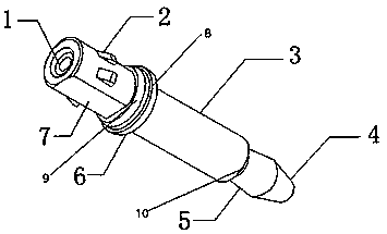
[0013] Such as figure 1 As shown, a new type of optical fiber adapter tube, which includes a main body 3, the upper part of the main body 3 is connected with a fixed disk 6, a gasket 8 is arranged above the fixed disk 6, and a rubber is arranged above the gasket 8 Ring 9, the main body 3 is connected with the adapter 7, several bumps 2 are arranged on the adapter 7, and the top of the adapter 7 is provided with a socket 1, and the bottom of the main body 3 is connected with the receiving pipe 5, so The receiving tube 5 is connected to the metal tail tube 4 , and the main body 3 is provided with an optical fiber inner tube hole 10 .

[0014] The diameters of the connections between the receiving pipe and the metal tail end pipe are equal.

[0015] The bump has a symmetrical structure with


PUM


Abstract

The invention discloses a novel optical fiber adapter tube which comprises a main body, wherein the upper part of the main body is connected with a fixed disc, a gasket is arranged above the fixed disc, a rubber ring is arranged above the gasket, the main body is connected with an adapter, a plurality of bumps are arranged on the adapter, a bearing tube is connected with a metal tail end tube, andan optical fiber inner tube hole is formed in the main body. The novel optical fiber adapter tube is simple in structure, the two optical fibers can be permanently or separably connected together, aconnection part for protecting the parts is arranged, and vibration borne by the adapter can be effectively reduced through the rubber ring and the gasket.

Description


Claims


Application Information

Patent Timeline
Owner 丹阳亿仁通信设备有限公司
Why Eureka
Try Eureka