Clapper valve

Active Publication Date: 2017-08-17
SPM OIL & GAS INC
View PDF3 Cites 1 Cited by
  • Summary
  • Abstract
  • Description
  • Claims
  • Application Information

AI Technical Summary

Benefits of technology

[0059]In an example embodiment, when the biasing member is positioned between the cap and the hanger,

Problems solved by technology

Any vibration caused by, for example, turbulence in the flow of fluid through the clapper valve, often produces significant wear to the internal components of the clapper valve.
Moreover, the effectiveness of the clapper valve in preventing, or at le

Method used


Image

  • Clapper valve
  • Clapper valve
  • Clapper valve

Examples


Embodiment Construction

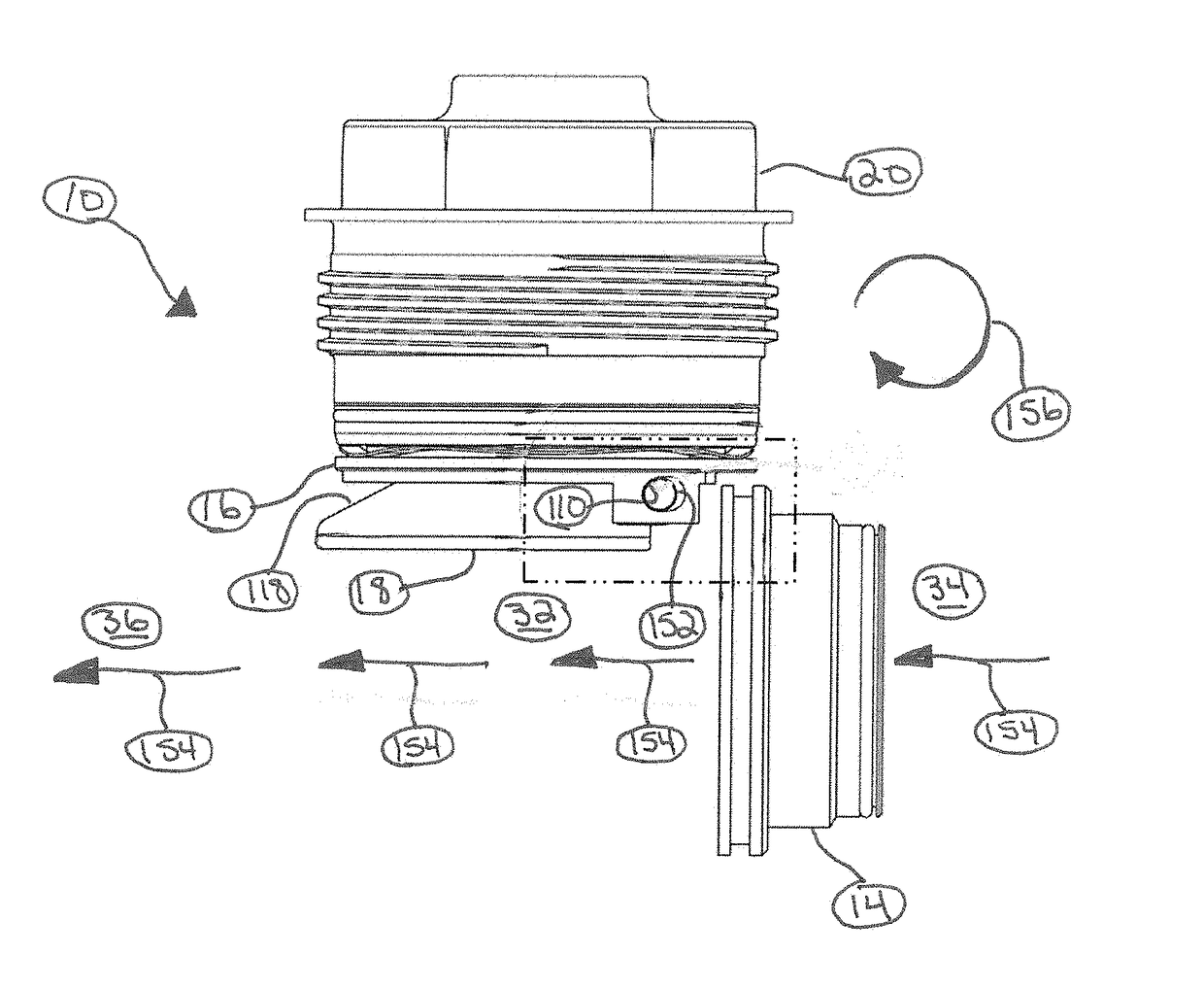
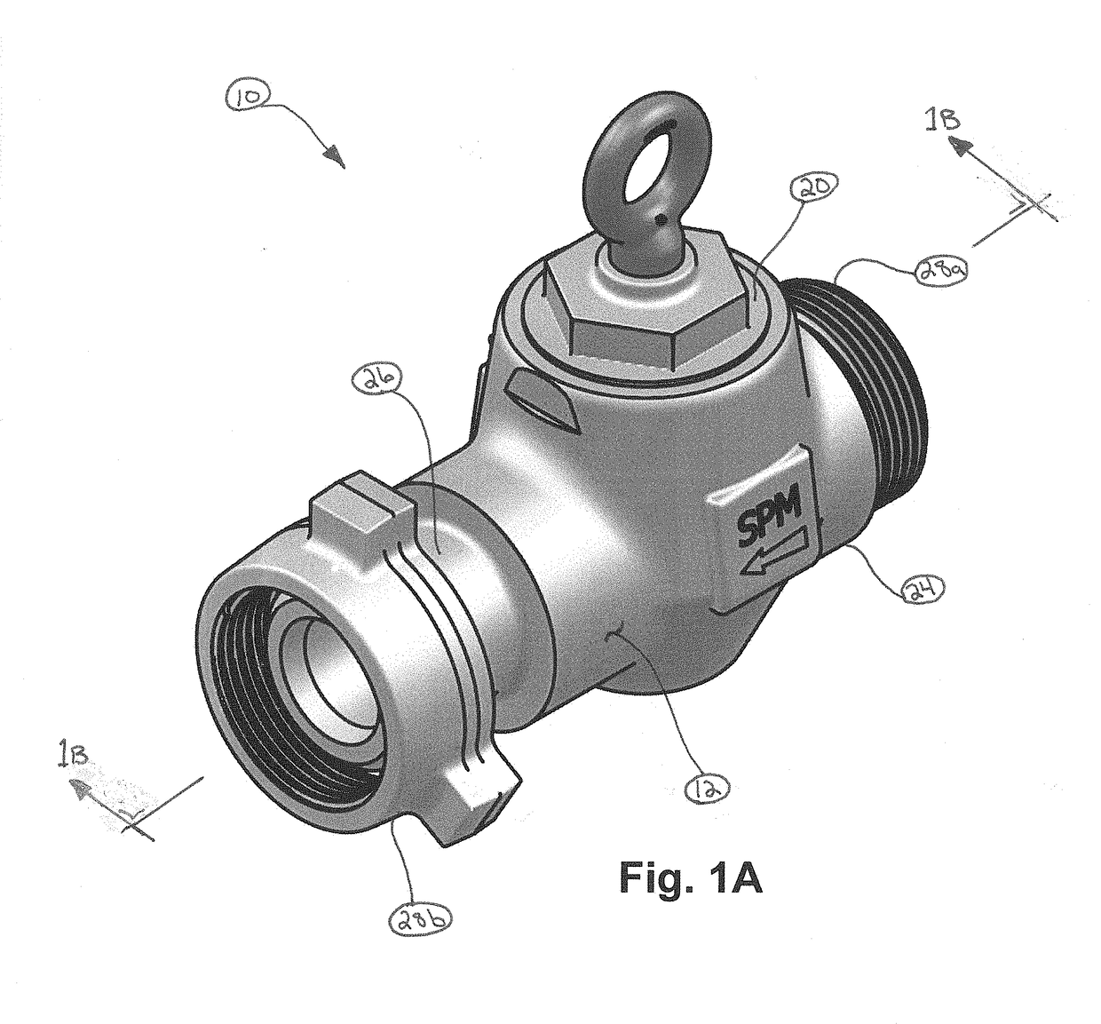
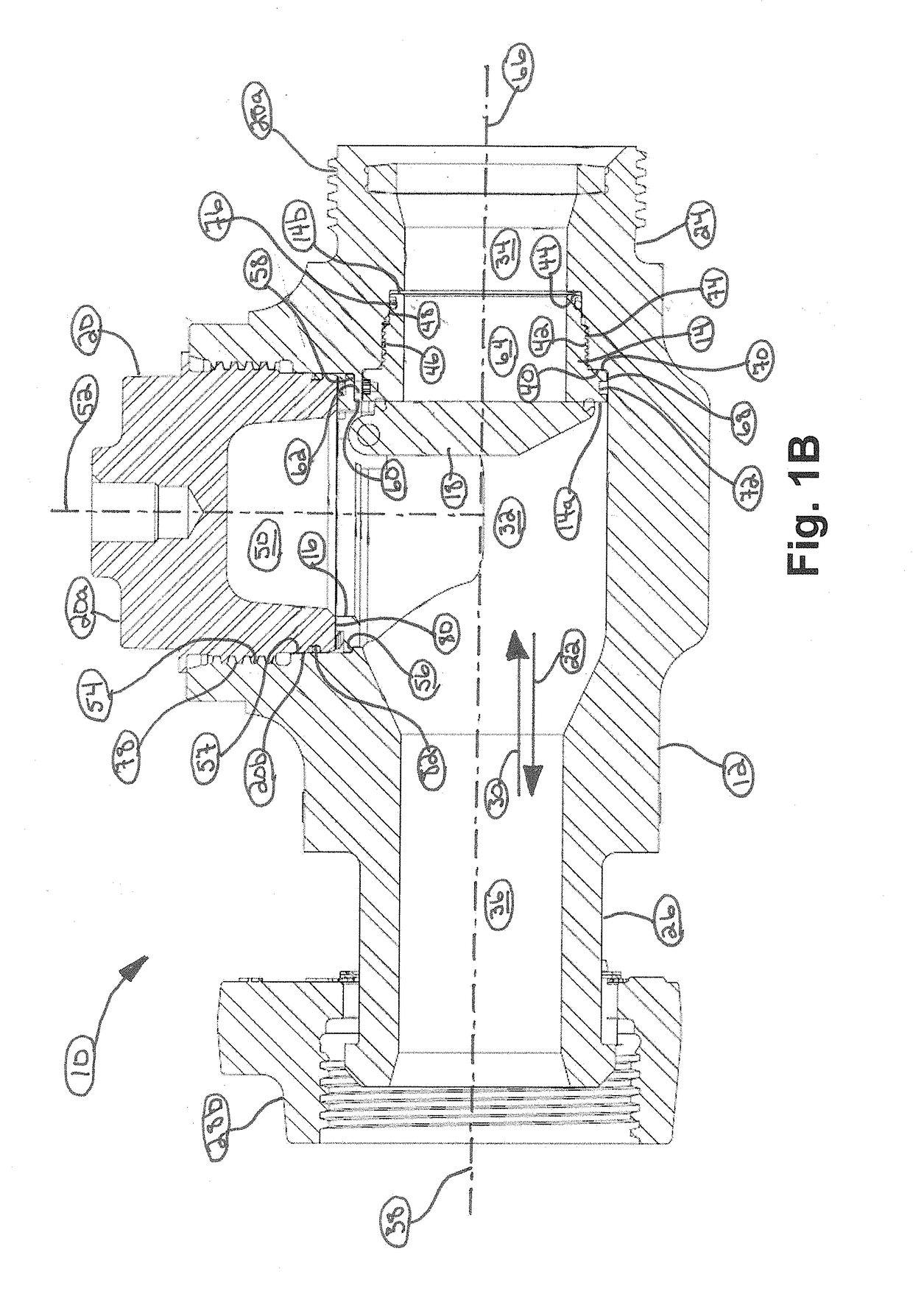
[0107]Referring initially to FIGS. 1A and 1B, an example embodiment of a clapper valve, generally referred to by the reference numeral 10, is illustrated. The clapper valve 10 includes a valve body 12; a valve seat 14 connected to the valve body 12; a hanger 16 extending within the valve body 12 proximate the valve seat 14; a clapper 18 pivotably connected to the hanger 16 and actuable between an open configuration, in which fluid flow is permitted through the valve body 12, and a closed configuration, in which the clapper 18 is seated against the valve seat 14 to at least partially restrict fluid flow through the valve body 12; and a cap 20 connected to the valve body 12 to secure the hanger 16 in position relative to the valve seat 14. The clapper valve 10 is adapted to be incorporated into a flowline through which fluid ordinarily flows in an axial direction 22. Accordingly, the valve body 12 includes an inlet end 24 and an outlet end 26. A pair of flowline connectors 28a and 28b ar


PUM


Abstract

A valve assembly adapted for use in oil and gas operations. In one aspect, the valve assembly includes a valve body defining an internal region, an inlet passageway, and an outlet passageway, the inlet and outlet passageways extending into the internal region; a valve seat connected to the valve body and defining a fluid passageway; a clapper extending within the internal region and defining an annular groove; and a seal extending within the annular groove of the clapper and adapted to sealingly engage the valve seat. In an example embodiment, the clapper is actuable between an open configuration, in which fluid flow is permitted through the fluid passageway; and a closed configuration, in which the seal sealingly engages the valve seat to at least partially restrict fluid flow through the fluid passageway.

Description


Claims


Application Information

Patent Timeline
Owner SPM OIL & GAS INC
Why Eureka
Try Eureka