Auxiliary nursing device for paralyzed patient

A technology for paralyzed patients and equipment, which is applied in the field of auxiliary nursing equipment for paralyzed patients, can solve problems such as labor and money consumption, inconvenience for people to take care of, and time-consuming to take care of paralyzed patients, and achieves the effect of reasonable structure and convenient operation.

Inactive Publication Date: 2019-05-24
杨思超
View PDF0 Cites 0 Cited by
  • Summary
  • Abstract
  • Description
  • Claims
  • Application Information

AI Technical Summary

Benefits of technology

This technology allows for better control over anesthesia machine by automatically changing its temperatures based on factors like blood flow or other conditions during surgery. It also ensures cleanliness without causing odors from waste products stored inside it's tank. Additionally, this system uses multiple components such as motors, sensors, valves, etc., making them easy-to use while maintaining their effectiveness. Overall, these feature enhance safety measures and make medical procedures more efficient.

Problems solved by technology

There are technical problem addressed in this patented text that currently requires nannies or anesthesia providers to help people with disabilities like spinal cord injuries who have difficulty moving around due to lack of mobility. These individuals often require specialized equipment such as catheters or other medical devices used by them during treatment. However these machines can be expensive and difficult to use at home without being able to work alongside those they were designed specifically for.

Method used


Image

  • Auxiliary nursing device for paralyzed patient
  • Auxiliary nursing device for paralyzed patient
  • Auxiliary nursing device for paralyzed patient

Examples


Embodiment Construction

[0020] The present invention will be further described below in conjunction with specific embodiments. The exemplary embodiments and descriptions of the present invention are used to explain the present invention, but not as a limitation to the present invention.

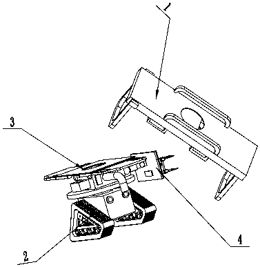
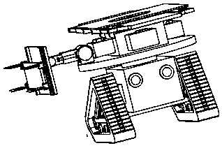
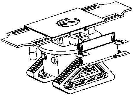
[0021] Example figure 1 , figure 2 , image 3 , Figure 4 , Figure 5 , Figure 6 , Figure 7 , Figure 8 , Figure 9 , Figure 10 As shown, a kind of auxiliary nursing equipment for paralyzed patients, including equipment matching bed part 1, walking part 2, washing support part 3, handling part 4, is characterized in that: the upper end surface of the large turntable 212 of the walking part 2 is connected with the washing The lower end surface of the flushing box 301 of the supporting part 3 is fixedly connected; the bottom end surface of the first rotating joint 401 of the carrying part 4 is fixedly connected with the upper end face of the large turntable 212 of the walking part 2, and the carrying plate 41


PUM


Abstract

The invention discloses an auxiliary nursing device for a paralyzed patient. The auxiliary nursing device comprises a device supporting bed portion, a walking portion, a flushing support portion and acarrying portion. The auxiliary nursing device is characterized in that the upper end surface of a large rotating disc of the walking portion is fixedly connected with the lower end surface of a flushing box of the flushing support portion; a carrying plate can be inserted into a carrying plate socket of the device supporting bed portion; when the patient needs to urinate or defecate, a first motor drives a first gear so as to drive the device to reach the side face of the device supporting bed portion; a second telescopic rod of the carrying portion cooperates with a second hydraulic cylinder to insert the carrying plate into the carrying plate socket; a first rotating joint keeps rotating clockwise, and a second rotating joint rotates counterclockwise, so that a second long plate remains stable; a pneumatic pump, a flushing box controller and a spray nozzle of the flushing support portion work cooperatively to flush a urine and excrement storage barrel, and urine and excrement are discharged into a toilet through a drain pipe.

Description


Claims


Application Information

Patent Timeline
Owner 杨思超
Why Eureka
Try Eureka