Infrared protocol based infrared code transmitting circuit, chip, remote controller and air conditioner

A technology of sending circuits and infrared codes, applied in the field of communication, can solve the problem of high power consumption, and achieve the effect of reducing power consumption and programming difficulty

Active Publication Date: 2019-06-07
GREE ELECTRIC APPLIANCES INC OF ZHUHAI
View PDF15 Cites 3 Cited by
  • Summary
  • Abstract
  • Description
  • Claims
  • Application Information

AI Technical Summary

Problems solved by technology

[0005] One purpose of the embodiment of the present invention is to provide an infrared code transmission circuit, chip, remote control device and air conditioner based on the infrared protocol, which solves the technical problem of high power consumption in the traditional technology

Method used


Image

  • Infrared protocol based infrared code transmitting circuit, chip, remote controller and air conditioner
  • Infrared protocol based infrared code transmitting circuit, chip, remote controller and air conditioner
  • Infrared protocol based infrared code transmitting circuit, chip, remote controller and air conditioner

Examples


Example Embodiment

[0033] In order to make the objectives, technical solutions and advantages of the present invention clearer, the following further describes the present invention in detail with reference to the accompanying drawings and embodiments. It should be understood that the specific embodiments described here are only used to explain the present invention, but not to limit the present invention.

[0034] The infrared code sending circuit based on the infrared protocol provided by the embodiment of the present invention can be applied to a chip. Among them, the chip can be combined with other peripheral circuit modules to form a remote control device. The user uses the remote control device to send an infrared signal matching the infrared protocol to the smart device to control the operation of the smart device. For example: the smart device is an air conditioner, and the user uses the remote control device to remotely control the air conditioner to stop running.

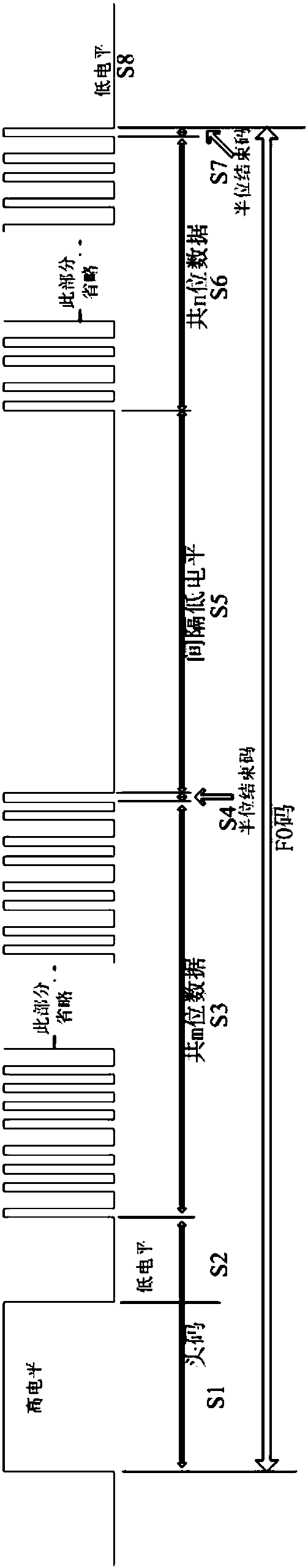
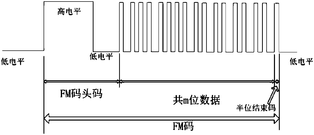
[0035] See figure 1 , figu


PUM


Abstract

The invention relates to an infrared protocol based infrared code transmitting circuit, a chip, a remote controller and an air conditioner, and belongs to the technical field of communication. The infrared code transmitting circuit comprises a carrier wave time length control module, a processing module and a carrier wave generation module; according to the stage and type of an infrared code to besent in infrared protocols, the processing module configures the carrier wave time length control module to generate an enablement signal; and according to the stage and type of the infrared code tobe sent in the infrared protocols, the carrier wave generation module generates a PWM type carrier wave signal, carries out logic operation on the PWM type carrier wave signal and the enablement signal, and generates and sends the infrared code to be sent. Thus, the infrared code sensing process can be completed by the infrared code transmitting circuit, the processing module can be in a dormancystate in the sending process, power consumption is reduced, and software programming is less difficult.

Description


Claims


Application Information

Patent Timeline
Owner GREE ELECTRIC APPLIANCES INC OF ZHUHAI
Why Eureka
Try Eureka