Low-speed large torque permanent magnet motor drive system for small space

A permanent magnet motor and drive system technology, applied in the direction of electric components, connected with control/drive circuits, electrical components, etc., can solve the problems of inconvenient installation and transportation, complex generator structure, high manufacturing cost, etc., and improve the utilization rate of materials , save material cost, and facilitate installation and maintenance

Pending Publication Date: 2019-06-14
日照东方电机有限公司
View PDF0 Cites 0 Cited by
  • Summary
  • Abstract
  • Description
  • Claims
  • Application Information

AI Technical Summary

Problems solved by technology

Since the volume of the motor is proportional to the electromagnetic torque, for the same motor, its power is proportional to the product of the motor speed and torque. Due to the effect of torque, the number of poles of the motor is often designed very large, and the structure of the generator becomes very complicated and bulky, requiring hoisting and maintenance of the whole machine. Therefore, this method has the disadvantages of large size, heavy weight, high manufacturing cost, and installation Inconvenient transportation and other issues

Method used


Image

  • Low-speed large torque permanent magnet motor drive system for small space
  • Low-speed large torque permanent magnet motor drive system for small space
  • Low-speed large torque permanent magnet motor drive system for small space

Examples


Example Embodiment

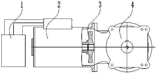
[0034] Embodiment one:

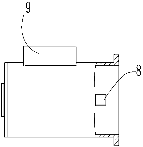
[0035]A low-speed, high-torque permanent magnet motor drive system for a small space, including a motor, a right-angled shaft reducer 4 movably coupled to the output shaft of the motor, and a frequency converter 1 flexibly connected to the motor. The motor is Low-speed high-torque permanent magnet synchronous motor 2, the output shaft of the low-speed high-torque permanent magnet synchronous motor 2 forms an angle of 90 degrees with the output shaft of the right-angle shaft reducer 4, and the output shaft of the low-speed high-torque permanent magnet synchronous motor 2 end and the input shaft end of the orthogonal shaft reducer 4 are connected by a spline coupling 3, the casing of the low-speed high-torque permanent magnet synchronous motor 2 is connected with the casing of the rectangular axis reducer 4, and the The machine 4 is a single-stage reducer, the middle part of the top of the low-speed high-torque permanent magnet motor is provided with an int

Example Embodiment

[0036] Embodiment two:

[0037] A low-speed, high-torque permanent magnet motor drive system for a small space, including a motor, a right-angled shaft reducer 4 movably coupled to the output shaft of the motor, and a frequency converter 1 flexibly connected to the motor. The motor is Low-speed high-torque permanent magnet synchronous motor 2, the output shaft of the low-speed high-torque permanent magnet synchronous motor 2 forms an angle of 90 degrees with the output shaft of the right-angle shaft reducer 4, and the output shaft of the low-speed high-torque permanent magnet synchronous motor 2 end and the input shaft end of the orthogonal shaft reducer 4 are connected by a spline coupling 3, the casing of the low-speed high-torque permanent magnet synchronous motor 2 is connected with the casing of the rectangular axis reducer 4, and the The machine 4 is a single-stage reducer, the output shaft end of the low-speed high-torque permanent magnet synchronous motor 2 is provided wi


PUM


Abstract

The invention discloses a low-speed large torque permanent magnet motor drive system for a small space. The system comprises a motor, a rectangular axis reducer actively connected on an output shaft of the motor, and a transducer flexibly connected on the motor, and the system is characterized in that the motor is a low-speed large torque permanent magnet synchronous motor, an output shaft of thelow-speed large torque permanent magnet synchronous motor and an output shaft of the rectangular axis reducer form a 90-degree included angle, the output shaft of the low-speed large torque permanentmagnet synchronous motor is linked with an input shaft of the rectangular axis reducer through a spline coupler, the shell of the low-speed large torque permanent magnet synchronous motor is connectedwith the shell of the rectangular axis reducer, and the rectangular axis reducer is a single-stage reducer. The low-speed large torque permanent magnet motor drive system has the beneficial effects that the low-speed large torque driver for the equipment has characteristics of small volume, light weight, low rotating speed, large torque, high efficiency and energy conservation, lower material cost, and convenience in installation and maintenance compared with traditional driving manner.

Description


Claims


Application Information

Patent Timeline
Owner 日照东方电机有限公司
Why Eureka
Try Eureka