Grain counting device

A technology of turntable and fixed column, applied in the field of pellet counter, can solve the problems of pellet pollution, time-consuming and laborious, affecting drug quality, etc., and achieve the effect of good sealing and avoiding spillage.

Pending Publication Date: 2019-06-18
TIANJIN VOCATIONAL INST
View PDF0 Cites 0 Cited by
  • Summary
  • Abstract
  • Description
  • Claims
  • Application Information

AI Technical Summary

Problems solved by technology

For this kind of pill-shaped medicine, most of the methods used by patients at present are to pour the pills into the palm of the hand or other containers to determine the quantity. If too many pills are poured out, they need to be poured back into the bottle, so it is not possible A

Method used


Image

  • Grain counting device
  • Grain counting device
  • Grain counting device

Examples


Example Embodiment

[0029] The pellet counter of the present invention will be described in detail below with reference to the accompanying drawings.

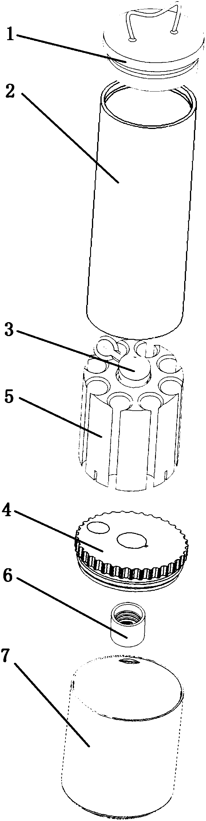
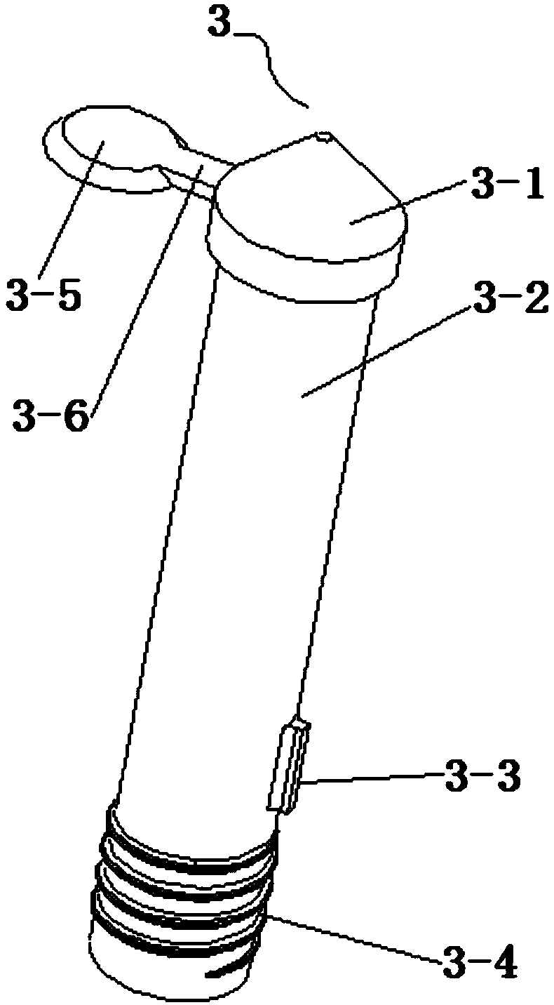
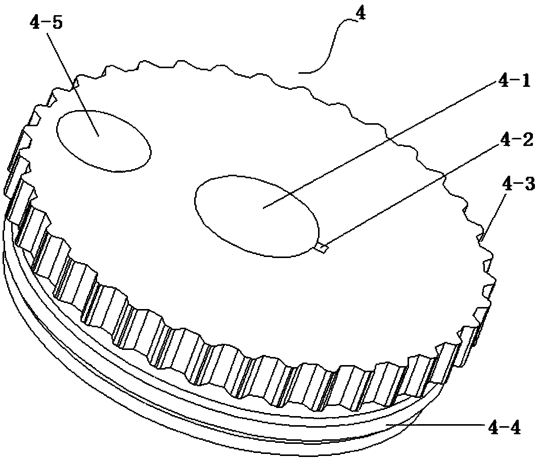
[0030] As attached Figure 1~5 As shown, it includes: a cylindrical shell 2, a central column 3, a turntable 4, and a fixed column 5 (cylinder). The radius of the turntable 4 is greater than the radius of the fixed column 5, and the fixed column 5 is placed above and connected to the turntable 4 4 coaxially arranged, a second center hole 5-2 is formed at the center position (circle center position) of the fixed column 5, and a first center hole 4-1 is formed at the center position (circle center position) of the turntable 4, and the center column 3 A protruding limit part 3-1 is formed at the upper end, and the central column below the limit part is a column 3-2, such as figure 2 As shown, the upper end of the limiting portion 3-1 is formed with a downwardly inclined inclined surface in the radial direction, so that the pills on the top of the limiting


PUM


Abstract

The invention discloses a grain counting device. The grain counting device comprises a cylindrical outer shell, a central column, a rotating disc and a fixing column, the fixing column is placed abovethe rotating disc and is arranged coaxial with the rotating disc, a second central hole is formed in the center of the fixing column, a first central hole is formed in the center of the rotating disc, a protruding limiting portion is formed at the upper end of the central column, the lower end of the central column sequentially penetrates through the first central hole and the second central holeand is in threaded connection with a bottom support, the limiting portion and the bottom support tightly press the fixing column and the rotating disc, a plurality of medicine placing through holes which are arranged at intervals are formed in the fixing column in the circumferential direction by taking the second central hole as the circle center, the outer shell is arranged on the fixing column, and a medicine baffle plate is connected to the limiting portion. Pills needing to be counted out through the grain counting device are placed in each medicine placing through hole, and by rotatingthe rotating disc, when a medicine leaking through hole is located under one certain medicine placing through hole, the pills in the certain medicine placing through hole are discharged through the medicine leaking through hole, so that accurate grain counting is realized.

Description


Claims


Application Information

Patent Timeline
Owner TIANJIN VOCATIONAL INST
Why Eureka
Try Eureka