Touch sensing module and touch display panel and electronic device using same
A touch display panel and touch sensing technology, which is applied in electrical digital data processing, input/output process of data processing, instruments, etc., can solve the problems of high energy consumption, cumbersome process, low space utilization, etc.
- Summary
- Abstract
- Description
- Claims
- Application Information
AI Technical Summary
Benefits of technology
Problems solved by technology
Method used
Image

Examples
no. 1 example
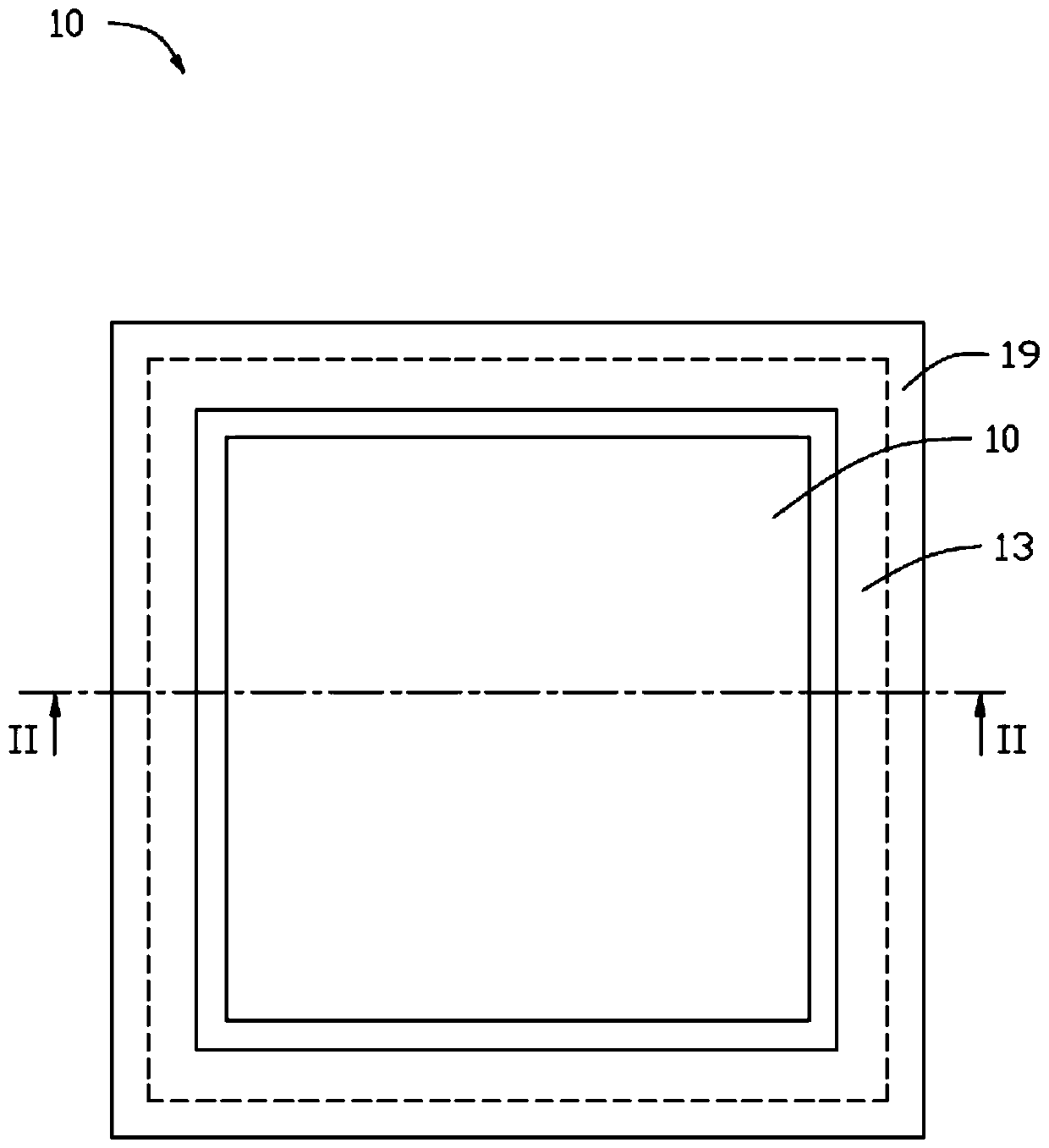
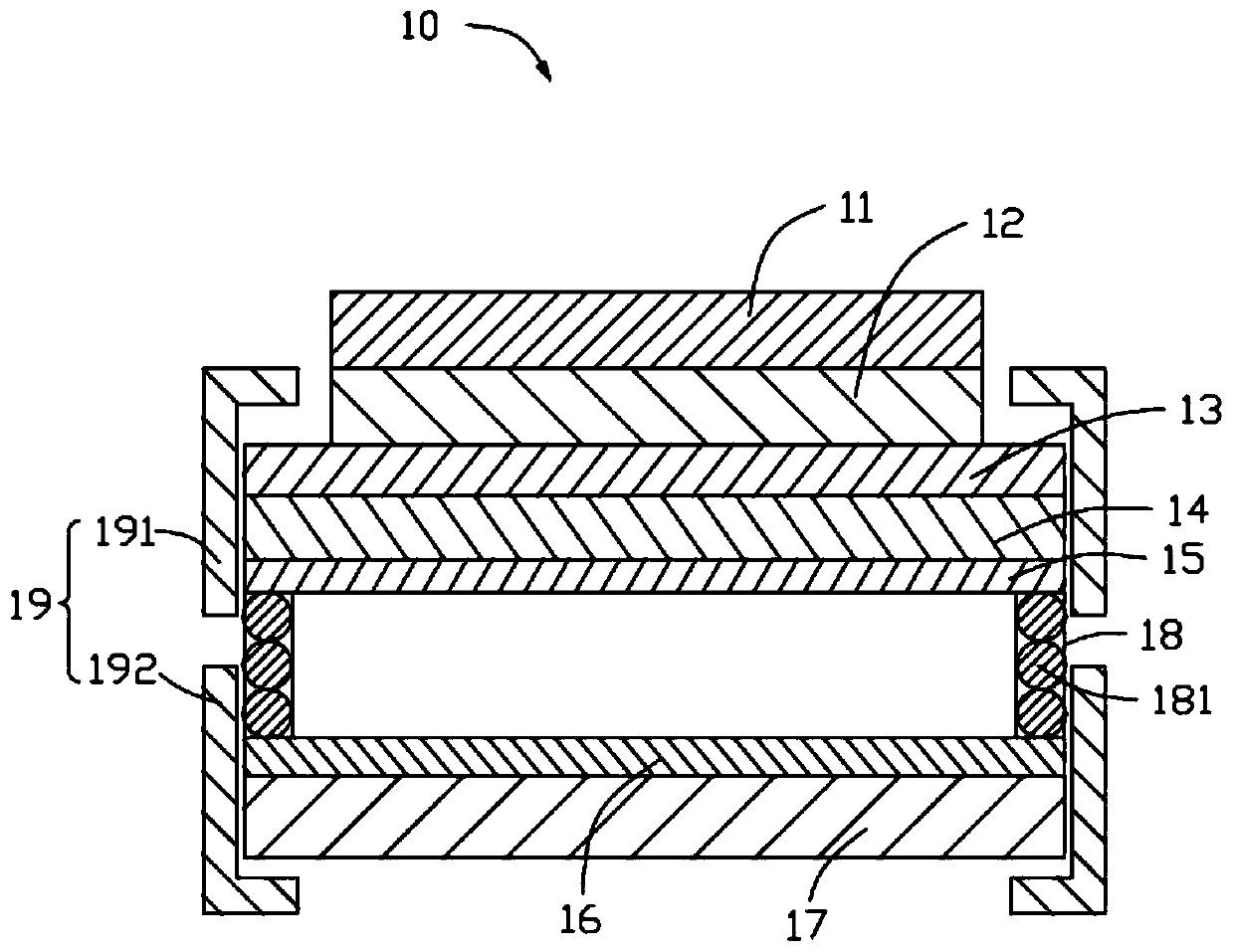
[0030] Such as figure 1 As shown, it is a schematic top view of the touch sensing module 10 according to an embodiment of the present invention, as figure 2 As shown, it is a schematic cross-sectional view of the touch sensing module 10 according to an embodiment of the present invention. The touch sensing module 10 includes a touch sensing layer 12, an insulating layer 14, a first pressure sensing layer 15 and a second pressure sensing layer 16, and the touch sensing layer 12 is arranged on one side of the insulating layer 14 for Sensing the touch position, the first pressure sensing layer 15 and the second pressure sensing layer 16 are arranged on the side of the insulating layer 14 away from the touch sensing layer 12 for sensing touch pressure, the first pressure sensing layer 15 and the second pressure sensing layer The two pressure-sensing layers 16 are arranged at intervals, and the projections of the first pressure-sensing layer 15 and the second pressure-sensing layer
no. 2 example
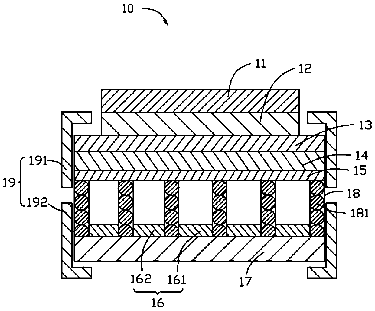
[0038] Such as figure 1 As shown, it is a schematic top view of the touch sensing module 10 according to an embodiment of the present invention, as image 3 As shown, it is a schematic cross-sectional view of the touch sensing module 10 according to an embodiment of the present invention. The touch sensing module 10 includes a touch sensing layer 12, an insulating layer 14, a first pressure sensing layer 15 and a second pressure sensing layer 16, and the touch sensing layer 12 is arranged on one side of the insulating layer 14 for Sensing the touch position, the first pressure sensing layer 15 and the second pressure sensing layer 16 are arranged on the side of the insulating layer 14 away from the touch sensing layer 12 for sensing touch pressure, the first pressure sensing layer 15 and the second pressure sensing layer The two pressure-sensing layers 16 are arranged at intervals, and the projections of the first pressure-sensing layer 15 and the second pressure-sensing layer 1
no. 3 example
[0046] Such as figure 1 As shown, it is a schematic top view of the touch sensing module 10 according to an embodiment of the present invention, as Figure 4 As shown, it is a schematic cross-sectional view of the touch sensing module 10 according to an embodiment of the present invention. The touch sensing module 10 includes a touch sensing layer 12, an insulating layer 14, a first pressure sensing layer 15 and a second pressure sensing layer 16, and the touch sensing layer 12 is arranged on one side of the insulating layer 14 for Sensing the touch position, the first pressure sensing layer 15 and the second pressure sensing layer 16 are arranged on the side of the insulating layer 14 away from the touch sensing layer 12 for sensing touch pressure, the first pressure sensing layer 15 and the second pressure sensing layer The two pressure-sensing layers 16 are arranged at intervals, and the projections of the first pressure-sensing layer 15 and the second pressure-sensing layer
PUM
 Abstract
Description
Claims
Application Information
 - R&D Engineer
- R&D Manager
- IP Professional
- Industry Leading Data Capabilities
- Powerful AI technology
- Patent DNA Extraction
Browse by: Latest US Patents, China's latest patents, Technical Efficacy Thesaurus, Application Domain, Technology Topic.
© 2024 PatSnap. All rights reserved.Legal|Privacy policy|Modern Slavery Act Transparency Statement|Sitemap