Biopsy-taking drill

A biopsy and drilling technology, applied in the fields of medical science, inoculation and ovulation diagnosis, diagnosis, etc., can solve the problems of insufficient bone and bone loss, so as to ensure sufficient bone, avoid bone loss, and avoid multiple bone loss. The effect of collection

Pending Publication Date: 2019-07-23
HEBEI RUIHE MEDICAL DEVICES CO LTD
View PDF0 Cites 0 Cited by
  • Summary
  • Abstract
  • Description
  • Claims
  • Application Information

AI Technical Summary

Problems solved by technology

[0003] The purpose of the present invention is to provide a biopsy drill to solve the technical problem in the prior art tha

Method used


Image

  • Biopsy-taking drill
  • Biopsy-taking drill
  • Biopsy-taking drill

Examples


Embodiment approach

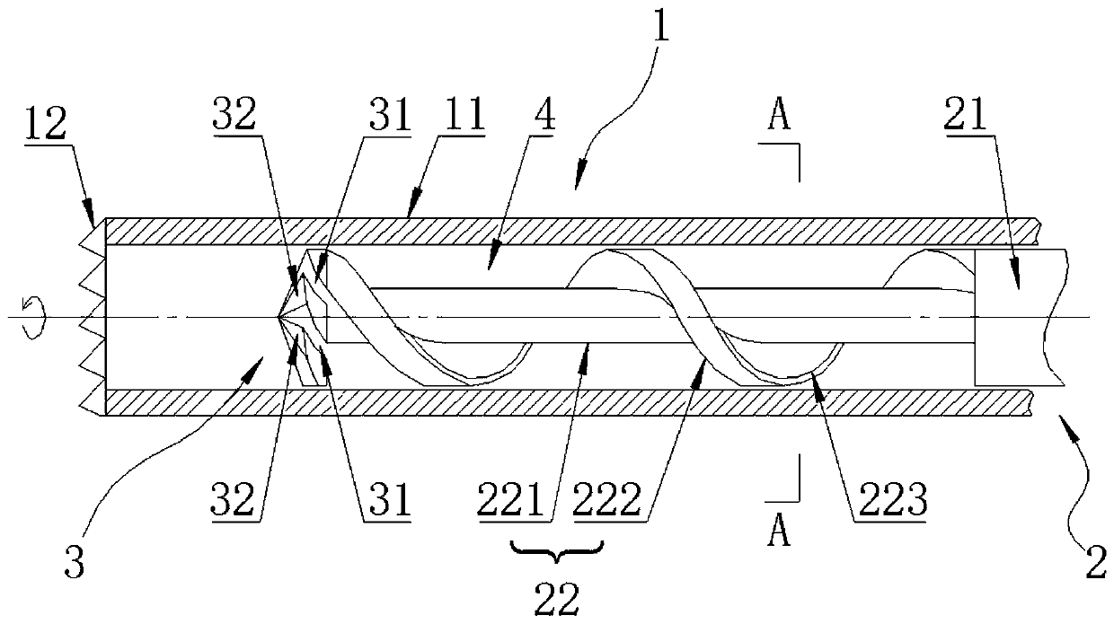
[0038] Please also refer to figure 1 , as a specific embodiment of the biopsy drill provided by the present invention, the drill rod 2 includes a connecting rod 21 and a screw rod 22 .

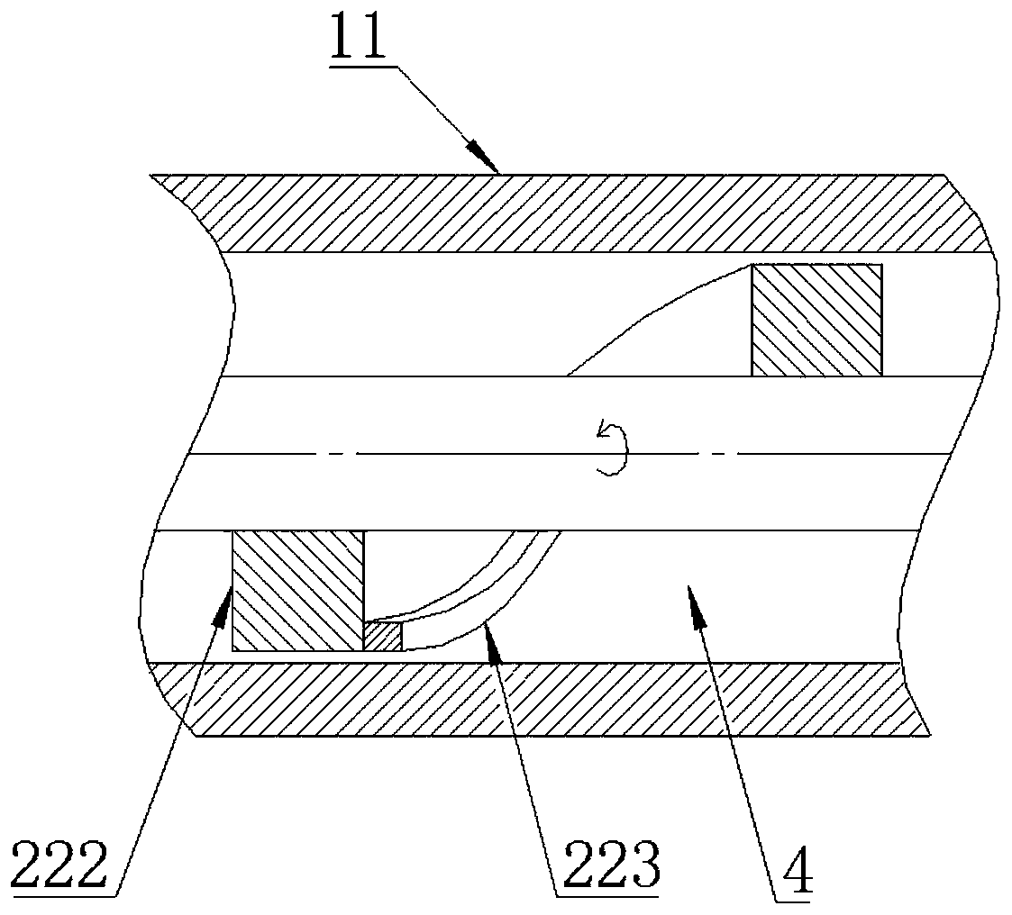
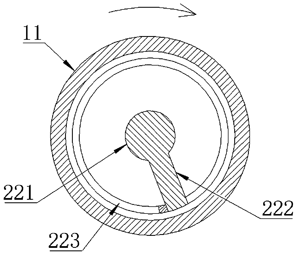
[0039] Connecting rod 21 is used for being connected with drilling machine. The rear end of the screw rod 22 is connected to the front end of the connecting rod 21, and the front end is connected to the drill bit 3; the rear end face of the drill bit 3, the outer wall of the screw rod 22, the front end face of the connecting rod 21 and the outer drill The cavity 4 of the helical structure is formed between the inner walls of the tube 1 .

[0040] Specifically, the connecting rod 21 may be cylindrical, and the rear end is provided with a clamping section with a square section for being clamped by the chuck of the drilling machine. The front end of the connecting rod 21 blocks the rear side of the cavity 4 . The screw rod 22 can divide the cavity 4 into a helical structure, and when the screw ro

specific Embodiment approach

[0055] Please also refer to figure 1 , as a specific embodiment of the biopsy drill provided by the present invention, the drill bit 3 includes a main body and a plurality of main cutting edges 32 .

[0056] The outer periphery of the main body is provided with the chip removal groove 31 . A plurality of main cutting edges 32 are arranged on the front end surface of the main body and distributed at equal angular intervals along the radial direction of the main body, and the front ends of the chip removal flutes 31 communicate with the gap between two adjacent main cutting edges 32 .

[0057] Specifically, a plurality of spiral flutes 31 are coaxially provided on the outer periphery of the main body. The front end of the main body is a pyramid with a protruding tip, and a plurality of main cutting edges 32 are respectively arranged along the side edges of the taper, so that a plurality of main cutting edges 32 are radially distributed on the front end surface of the main body wi


PUM


Abstract

The invention provides a biopsy-taking drill, and belongs to the field of orthopaedic medical equipment, including: an outer drill pipe, a drill rod, a drill bit and a cavity. The outer drill pipe isarranged for drilling into bones; the drill rod is arranged in the outer drill pipe in a penetrated manner, and can make the axial movement along the outer drill pipe; the drill bit is arranged at thefront end of the drill rod and provided with chip removal grooves, and the outer wall of the drill bit is attached to the inner wall of the outer drill pipe; the cavity for storing sclerotin is formed between the back face of the drill bit, the outer wall of the drill rod and the inner wall of the outer drill pipe in a surrounded mode; and the chip removal grooves are connected to the cavity. When the biopsy-taking drill is drilled, the sclerotin is cut up and stored in the cavity through the drill bit, and the drill bit and the drilling rod can be guided by the outer drill pipe. When the biopsy-taking drill is taken out, in the process of withdrawing the outer drill pipe, the drill rod and the drill bit from the bone, the outer drill pipe prevents the sclerotin from falling from the outer-side opening of the cavity, and the drill bit prevents the sclerotin from falling from the front-end opening of the cavity. Through the above structures, the falling of sclerotin is avoided, sufficient sclerotin collection is ensured, and multiple sclerotin collection is avoided, without causing unnecessary suffering to the patients.

Description


Claims


Application Information

Patent Timeline
Owner HEBEI RUIHE MEDICAL DEVICES CO LTD
Why Eureka
Try Eureka