Aero-engine high-pressure fuel and grease heat radiator

An aero-engine and radiator technology, which is applied in the direction of engine lubrication, engine components, machines/engines, etc., can solve the problems of heavy system weight, inconvenient maintenance, affecting installation, etc., to reduce system pipelines and reduce maintenance requirements. , the effect of improving reliability

Inactive Publication Date: 2019-07-23
GUIZHOU YONGHONG AVIATION MACHINERY
View PDF7 Cites 5 Cited by
  • Summary
  • Abstract
  • Description
  • Claims
  • Application Information

AI Technical Summary

Benefits of technology

This patented technology describes an improved type of air conditioning (Air Condition) equipment used in aircraft engines that includes both primary coolers and secondary refrigerators. These devices have different types of components such as pumps, motors, filters, etc., depending upon their purpose and function they serve. To prevent damage from excessive pressure fluctuations during flight operations, these systems require some form of safety features like shutdown valves when there're too much water entering them due to rain or snow melting. However, this can be challenged because it requires integration between separate parts within one device called the main component of the Radiator Core System.

Problems solved by technology

This patented technical problem addressed in this patents relates to improving the efficiency or performance of gas turbine engines used in airplanes during flight operations. By utilizing these systems with advanced technology such as liquid oxygen (LOX) injection techniques, they have improved thermal management capabilities compared to older designs without any modifications. Additionally, there may also include various components like sensors and actuation devices attached to the engine itself. These improvements make installation, maintenance, operation more convenient than previous versions of existing design options.

Method used


Image

  • Aero-engine high-pressure fuel and grease heat radiator
  • Aero-engine high-pressure fuel and grease heat radiator
  • Aero-engine high-pressure fuel and grease heat radiator

Examples


Embodiment Construction

[0027] The technical solution of the present invention will be further described below in conjunction with the accompanying drawings, but the claimed protection scope is not limited to the description.

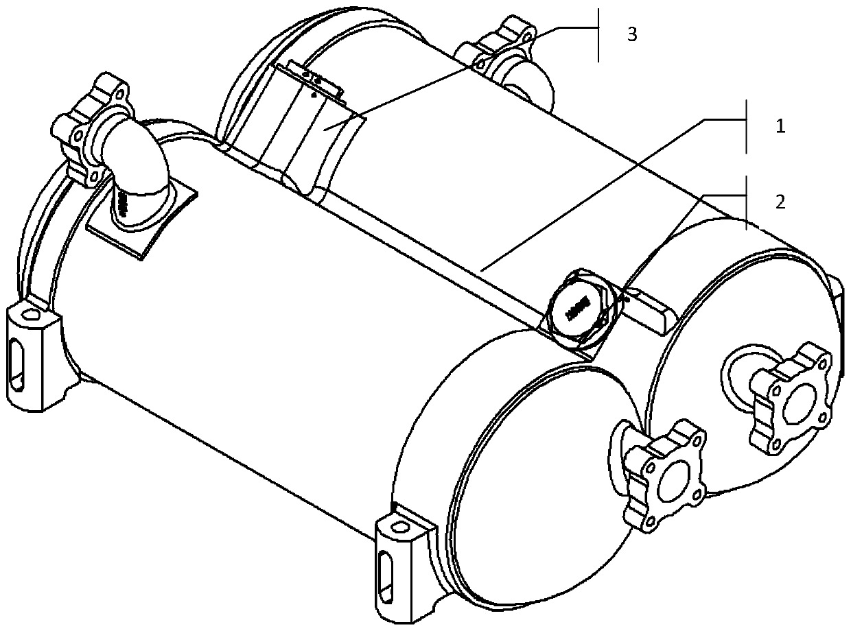
[0028] Such as figure 1 Shown is a structural diagram of a double-core structure high-pressure fuel oil radiator of the present invention. On the whole, the structure is mainly composed of a double-core body fuel oil radiator assembly 1, a fuel safety bypass valve 2, and oil The safety bypass valve 3 is composed of a fuel / lubricating oil safety valve that is assembled and connected with the double-core fuel and lubricating oil radiator assembly 1 by threads.

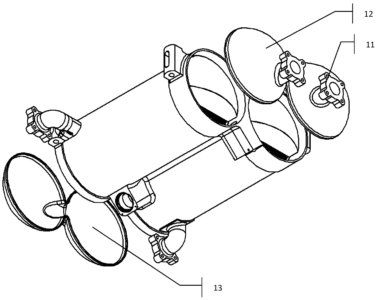
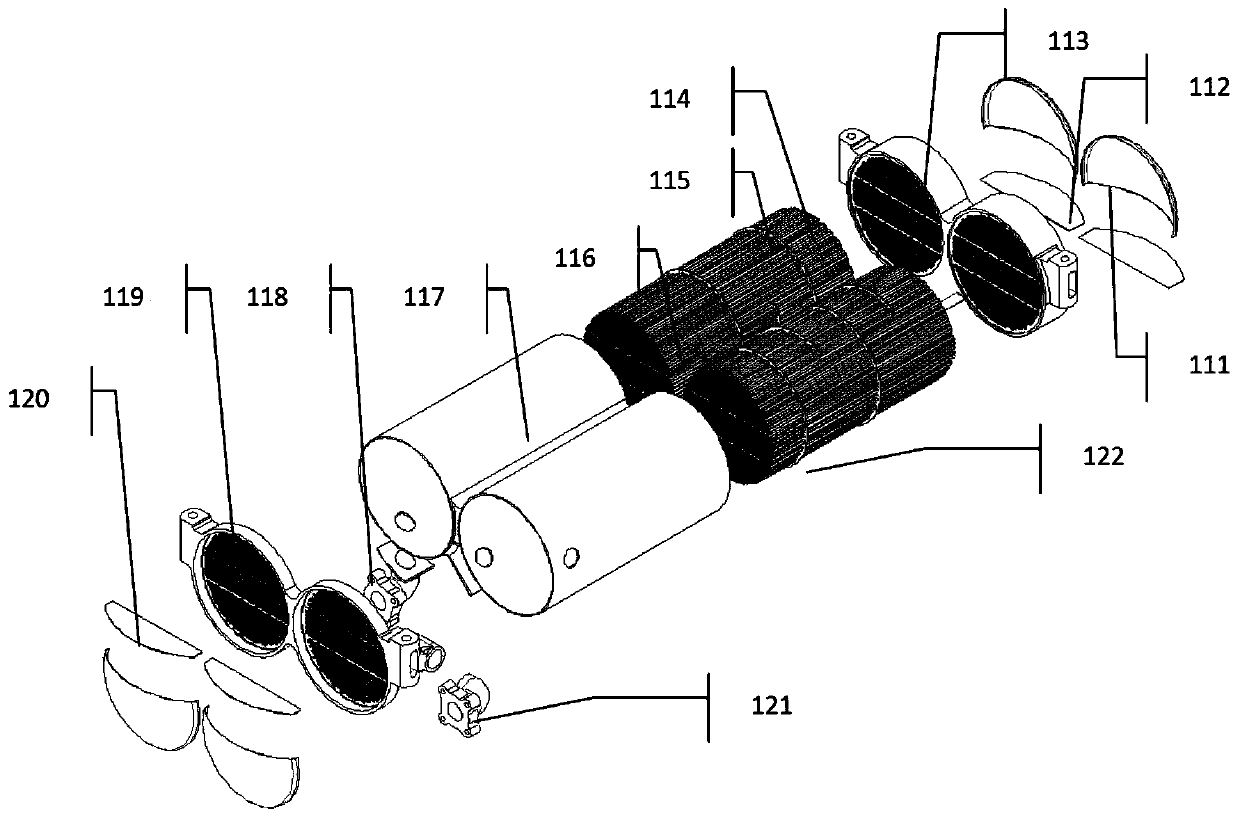
[0029] Such as figure 2 As shown, it is a schematic diagram of a double-core fuel oil radiator assembly 1 in a high-pressure fuel oil radiator with a double-core structure of the present invention, which mainly consists of a double-core fuel oil radiator core 10, a fuel inlet ball Cover 11, fuel outlet spherical cover


PUM


Abstract

The invention discloses an aero-engine high-pressure fuel and grease heat radiator. The heat radiator comprises a double-core-body fuel and grease heat radiator assembly (1), a fuel safety bypass valve (2) and an oil safety bypass valve (3). The high-temperature low-pressure oil flows along a shell pass of the double-core-body fuel and grease heat radiator assembly (1), and a low-temperature high-pressure fuel flows along a tube pass of the double-core-body fuel and grease heat radiator assembly (1). Heat of the oil is taken away by the fuel through heat exchange, so that the high-temperatureoil is cooled. The fuel safety bypass valve (2) and the oil safety bypass valve (3) are only started in the case that an engine fuel system becomes abnormal or an engine oil system becomes abnormal orflowing resistance of the fuel or flowing resistance of the oil of a heat radiator core body is increased during working in alpine region, the fluid does not flow through the heat radiator core body,so that the use safety of an engine is ensured. According to the heat radiator, the structure of the double-core-body fuel and grease heat radiator assembly is mainly designed, so that the effects that the heat exchange efficiency is highest, the structure is the most compact, and the weight is lightest within a certain space and certain size range are achieved, and the use requirements of a newly-developed-model engine can be met.

Description


Claims


Application Information

Patent Timeline
Owner GUIZHOU YONGHONG AVIATION MACHINERY
Why Eureka
Try Eureka