High-efficiency energy-saving peanut picking equipment
A high-efficiency, energy-saving, peanut technology, applied in the field of agricultural equipment, can solve the problems of high labor intensity in peanut harvesting, affecting subsequent operations, and insufficient labor, achieving good taste and oil yield, reducing post-processing procedures, and improving cleanliness. Effect
- Summary
- Abstract
- Description
- Claims
- Application Information
AI Technical Summary
Problems solved by technology
Method used
Image

Examples
Example Embodiment
[0020] Example 1:
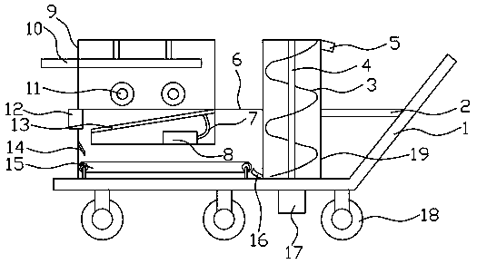
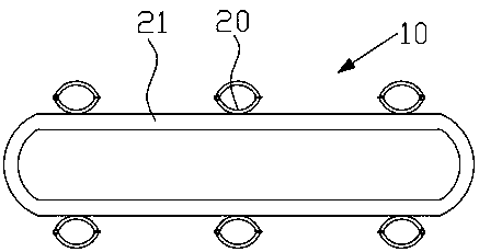
[0021] Such as Figure 1~5 As shown, the high-efficiency and energy-saving peanut picking equipment includes a rack 1, a peanut transport box 6 is provided at the front of the rack 1, a transfer box 19 is connected to the rear end of the peanut transport box 6, and a peanut beating box 9 is connected to the upper end of the peanut transport box 6. A rotating frame 10 is connected to the top of the peanut beating box 9. The rotating frame 10 includes a rotating belt 21 that rotates and a snap ring 20 for limiting the position of the peanut seedlings. The lower end of the peanut beating box 9 is connected with a roller 11 for generating a rotating beating force. The uprooted peanut seedlings are sent to the peanut beating box 9. The peanuts at the roots of the peanut seedlings are beaten and dropped into the peanut transport box 6 and transported to the transfer box 19 for collection. This equipment can achieve continuous peanuts Picking has high efficiency in pic
Example Embodiment
[0028] Example 2:
[0029] This example is a further optimization scheme based on Example 1: The preferred preparation method of the sponge in the sponge layer 3a is: by weight, 90 parts of trimethylolpropane polyether and 30 parts of toluene diisocyanate are mixed Mix in a container, stir evenly, and heat to 26°C, then take 8 parts of nano sepiolite powder, 14 parts of E-12 epoxy resin, 0.4 parts of stannous octoate, and 0.02 parts of diphenyl (1-methylpyrrolidine- 2)-Methanol, 0.08 parts of zinc acetate, put into the mixer and mix, heat to 50 ℃, high-speed stirring for 17 seconds, pour into the mold to foam and solidify to obtain a highly elastic sponge, in which diphenyl (1-methyl) The mass of (S)-diphenyl(1-methylpyrrolidine-2)-methanol and (R)-diphenyl(1-methylpyrrolidine-2)-methanol in pyrrolidine-2)-methanol The ratio is 1:0.67. The added diphenyl (1-methylpyrrolidine-2)-methanol and stannous octoate have a synergistic effect, which not only speeds up the foaming and crossli
Example Embodiment
[0031] Example 3:
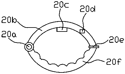
[0032] Such as Figure 1~5 As shown, the working principle of the device is: in the initial state, there is no suction between the fixed ring 20b and the moving ring 20f, and the peanut seedling roots of the peanuts to be picked are directed close to the fixed ring 20b, and the pressure sensor 20c on the inner wall of the fixed ring 20b detects the pressure and The light sensor 20d does not detect that the external environment changes from dark to bright, so the electric wire embedded in the moving ring 20f is energized. The surface of the moving ring 20f generates a magnetic field and attracts the iron magnet 20e on the side of the fixed ring 20b. The ring 20 clamps the peanut seedlings. Under the rotation of the rotating belt 21, the peanut seedlings are brought into the peanut beating box 9, and the rolling and beating force generated by the roller makes the peanuts fall. The peanut seedlings after picking the peanuts are brought out of the peanut beating box
PUM
 Abstract
Description
Claims
Application Information
 - R&D Engineer
- R&D Manager
- IP Professional
- Industry Leading Data Capabilities
- Powerful AI technology
- Patent DNA Extraction
Browse by: Latest US Patents, China's latest patents, Technical Efficacy Thesaurus, Application Domain, Technology Topic.
© 2024 PatSnap. All rights reserved.Legal|Privacy policy|Modern Slavery Act Transparency Statement|Sitemap