Method for measuring radial expansion force during running of cable middle joint

A technology of cable intermediate joints and radial expansion, which is applied in measuring devices, force/torque/power measuring instruments, instruments, etc., can solve problems such as short circuit or interface arc, casualties, partial discharge, etc., and reduce fire and explosion of cable joints accidents, improve power supply reliability, and reduce the effects of maintenance tests

Inactive Publication Date: 2019-09-10
SICHUAN UNIV
View PDF5 Cites 3 Cited by
  • Summary
  • Abstract
  • Description
  • Claims
  • Application Information

AI Technical Summary

Problems solved by technology

Due to the inherent structure, manufacturing level, construction conditions and environmental factors, the cable intermediate joint is easy to become the weak link of the cable, and partial discharge, overload, short circuit or interface arc may occur during operation, causing the te

Method used


Image

  • Method for measuring radial expansion force during running of cable middle joint
  • Method for measuring radial expansion force during running of cable middle joint
  • Method for measuring radial expansion force during running of cable middle joint

Examples


Embodiment

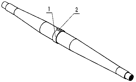
[0016] Such as figure 1 As shown, this embodiment provides a method for measuring the radial expansion force of the cable intermediate joint during operation, including an open ring sleeve wound on the cable intermediate joint and a mechanical sensor connected in series at the opening of the ring sleeve;

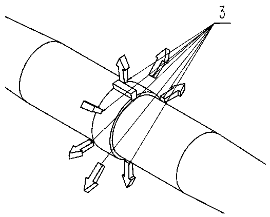
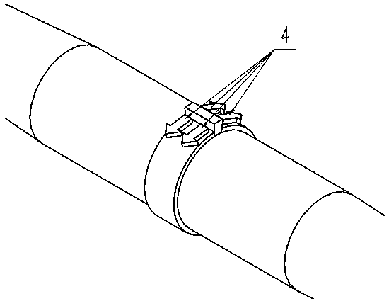
[0017] The open ring sleeve wound on the cable intermediate joint is used to bear the expansion force when the joint radially expands and convert the radial expansion force into a circumferential pulling force and transmit it to the mechanical sensor due to its incapable or micro-deformable nature; the series connection The mechanical sensor at the opening of the ring is used to collect the circumferential tension transmitted from the ring and has force value display and over-threshold alarm functions. After the installation is completed, the reading is artificially reset to zero and an early warning threshold is set. For the installation of the ring sleeve and the sensor, the


PUM


Abstract

The invention discloses a method for measuring radial expansion force during running of a cable middle joint. The method comprises an open loop and a mechanical sensor, wherein the middle cable jointis wound with the open loop; the mechanical sensor is connected in series to a loop opening; the open loop with which the cable middle joint is wound is used for carrying expansion force during radialexpansion of the joint, transforming the radial expansion force into circumferential tensile force by means of the own non-deformable or micro-deformation property, and transmitting the radial expansion force to the mechanical sensor; and the mechanical sensor which is connected in series to the loop opening is used for collecting the circumferential tensile force transmitted from the loop, and has a force value display function and a threshold exceeding alarm function. The method is reasonable in design. Through adoption of the method, the running state of the cable middle joint can be got immediately; unnecessary overhauling test and cable joint explosion accidents are reduced; and the power supply reliability is improved.

Description


Claims


Application Information

Patent Timeline
Owner SICHUAN UNIV
Why Eureka
Try Eureka