City bus wheel edge disc braking and flywheel energy-storage integrated braking device

A technology for urban public transport and flywheel energy storage, which is applied to brakes, brake components, vehicle components, etc., to achieve the effects of compact structure, high energy storage efficiency, and increased speed

Active Publication Date: 2019-09-17
JIANGSU UNIV OF TECH
View PDF7 Cites 3 Cited by
  • Summary
  • Abstract
  • Description
  • Claims
  • Application Information

AI Technical Summary

Benefits of technology

This patented technology combines two technical features - wired controlled disk (WCD) braking with flying battery powering. It uses an independent distribution model that eliminated all existing pipe lines while still allowing it to function properly. Additionally, when the car's engine stops running due to traffic jams, there are temporary stores inside the WCD drum where some stored energy may help start up again quickly without having to stop working altogether. Overall, this innovative design improves efficiency and economy by utilizing both conventional methods like hydrostatic pressure fluid and compressed air instead of relying on separate components such as springs.

Problems solved by technology

This patents discuss various technical problem addressed in this patented text: The technical problem presented during researching these new solutions relates to integrally controllable electronics or hybrid power train systems commonly found throughout metropolitan areas where modern transport means require more efficient operation than older ones due to their heavy weight and poor fuel economy. Existing methods involve complicated structures involving multiple parts including sensors, motors, valve mechanisms, and mechanical linkages. These limitations limit the design flexibility and adaptive capabilities required for optimal braking behavior under different road conditions.

Method used


Image

  • City bus wheel edge disc braking and flywheel energy-storage integrated braking device
  • City bus wheel edge disc braking and flywheel energy-storage integrated braking device
  • City bus wheel edge disc braking and flywheel energy-storage integrated braking device

Examples


Embodiment 1

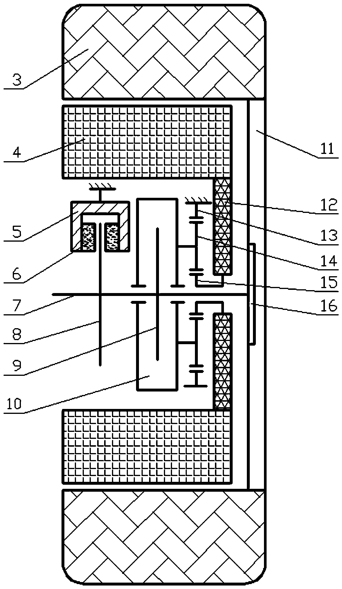
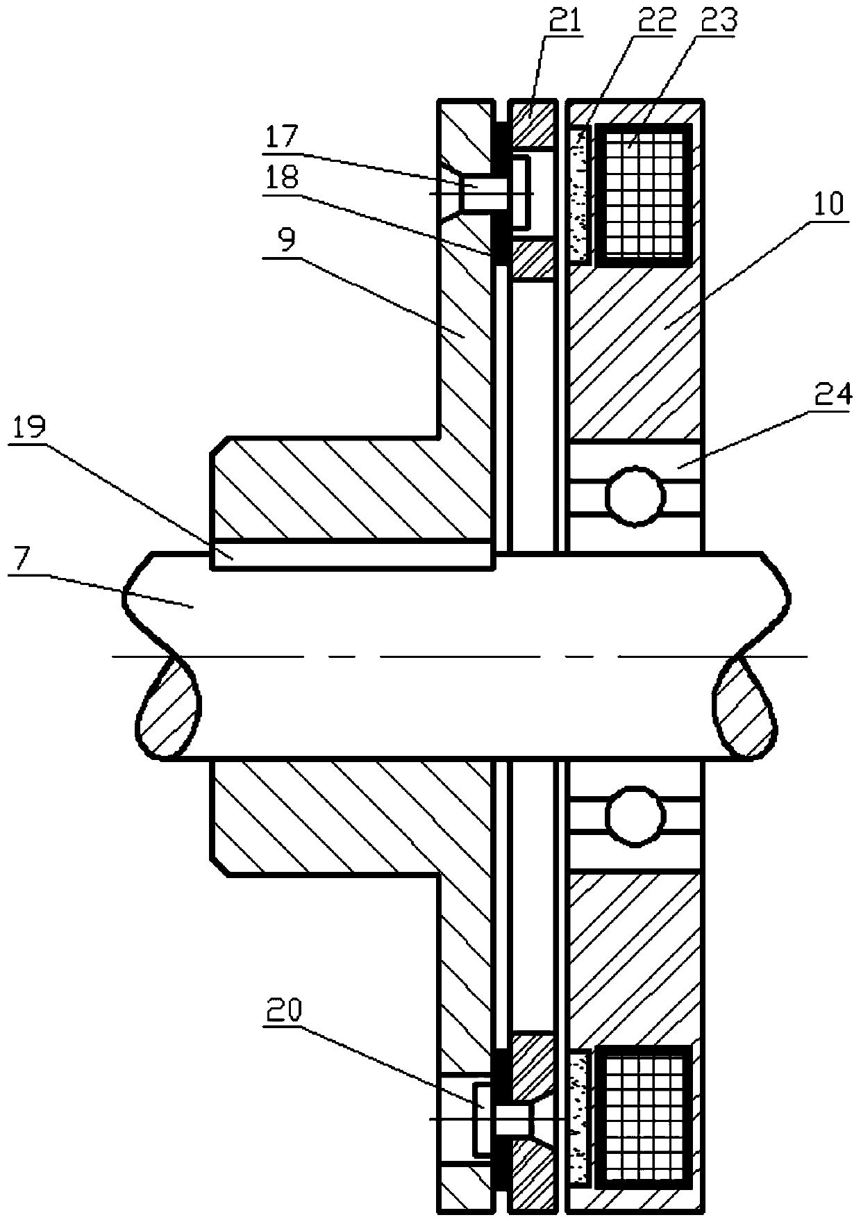
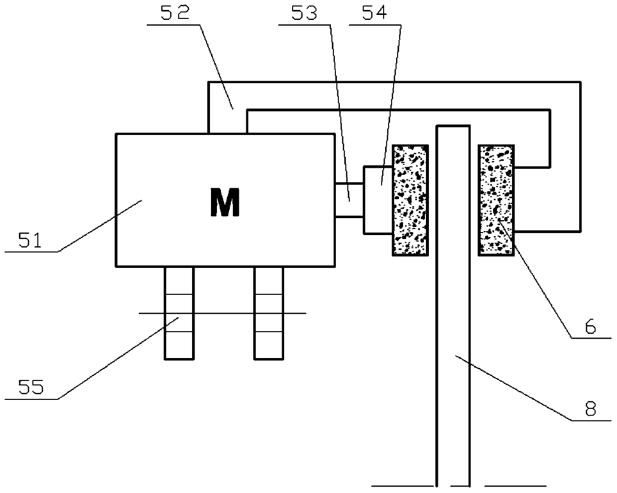
[0024] An urban bus wheel-side disc brake and flywheel energy storage integrated braking device, including a disc brake, an electromagnetic clutch, a planetary gear mechanism and a flywheel assembly, and the above-mentioned components are independently installed on the inside of each wheel hub 11 in a distributed arrangement , the wheel hub 11 is fixedly connected with the half shaft 7 through the half shaft flange 16, the automobile tire 3 and the wheel hub 11 rotate together with the half shaft 7, and the electromagnetic clutch is used to control the connection or separation of the energy storage flywheel 4 and the half shaft 7, The planetary gear mechanism is used to increase the speed of the energy storage flywheel 4 in the flywheel assembly. When the disc brake in the car brakes, the electromagnetic clutch is engaged, and the car tire 3 drives the energy storage flywheel 4 through the half shaft 7, the electromagnetic clutch and the planetary gear mechanism. Turning, transfor

Embodiment 2

[0036] Such as Figure 4 As shown, the basic structure and principle of the integrated braking device of this embodiment are similar to that of Embodiment 1, except that the diameter of the brake disc 8, the size and quantity of the flywheel support frame 12, and the energy storage flywheel 4 have been changed accordingly.


PUM


Abstract

The invention relates to the technical field of design vehicle braking, in particular to a city bus wheel edge disc braking and flywheel energy-storage integrated braking device. Wheel hubs are fixedly connected with half axles through half axle flanges, car tires and the wheel hubs rotate together with the half axles, electromagnetic clutches are used for controlling connecting or separating of energy-storage flywheels and the half axles, when a disc brake in a car conducts braking, the electromagnetic clutches are jointed, the car tires drive the energy-storage flywheels to rotate, and when the rotating speed of the energy-storage flywheels is higher than the rotating speed equivalent of the car tires, connection between the energy-storage flywheels and the car tires is broken off; and when the car is started, the electromagnetic clutches are jointed, the energy-storage flywheels provide auxiliary driving moment for the car tires, when the rotating speed of the energy-storage flywheels is lower than the rotating speed equivalent of the car tires, the electromagnetic clutches are separated, and connection between the energy-storage flywheels and the car tires is broken off. The city bus wheel edge disc braking and flywheel energy-storage integrated braking device integrates the functions and the advantages of drive-by-wire disc friction braking and flywheel energy storage, the structure is compact, response is rapid, and energy storage is efficient.

Description


Claims


Application Information

Patent Timeline
Owner JIANGSU UNIV OF TECH
Why Eureka
Try Eureka