Linear vibration actuator

A linear vibration and actuator technology, used in electric components, telephone communication, control of mechanical energy, etc., can solve problems such as inability to guarantee life, high vibration difficulties, etc., to prevent partial vibration, improve touch feeling, and drive noise.

Pending Publication Date: 2019-09-20
天津富禄通信技术有限公司
View PDF0 Cites 4 Cited by
  • Summary
  • Abstract
  • Description
  • Claims
  • Application Information

AI Technical Summary

Benefits of technology

This technology improves tactile sensation on lower frequency devices without causing unwanted movements or sounds that could make them harden overtime. It also prevents polarized motion caused by contact between the device's surface and other surfaces during use.

Problems solved by technology

This patented technical problem addressed in this patents relates to reducing the sizes required while maintaining good functionality (smallness) within small handheld mobile phone terminals without compromising their overall design features such as lightweight, thin profile, long battery lifetime, low power consumption, etc., especially when incorporated into smaller sized electronics like smartphones. To address these issues, researchers have focused on developing new types of vibrators called planar vibration motors, including those based on inductive forces generated between two parts separated by a cylindrical shaft made of metal material. These designs aim to provide better efficiency and longer lifespan under heavy use conditions.

Method used


Image

  • Linear vibration actuator
  • Linear vibration actuator
  • Linear vibration actuator

Examples


Embodiment Construction

[0034] In the following, the present invention can be modified variously, and can have various embodiments. Hereinafter, specific embodiments are shown in the drawings and described in detail. However, the present invention is not limited to these specific embodiments, and includes all modifications, equivalents, and replacements included in the spirit and technical scope of the present invention.

[0035] These examples are provided for the purpose of explaining in more detail to those skilled in the art. Therefore, in order to clearly illustrate and emphasize, the form of each component shown in the drawings will be enlarged. When describing the present invention, if it is considered that the specific description of the related known technology will confuse the gist of the present invention, it will be omitted. description of it.

[0036] Terms such as first and second can be used when describing various constituent elements, and the constituent elements should not be limited


PUM


Abstract

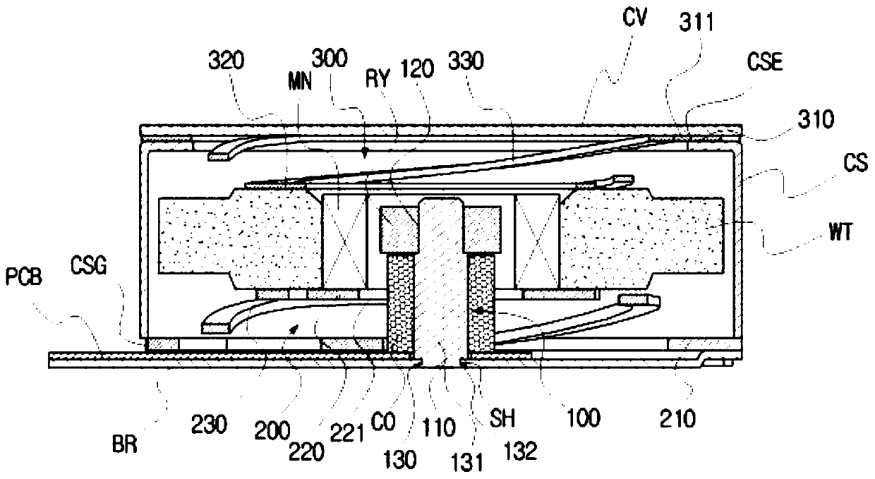
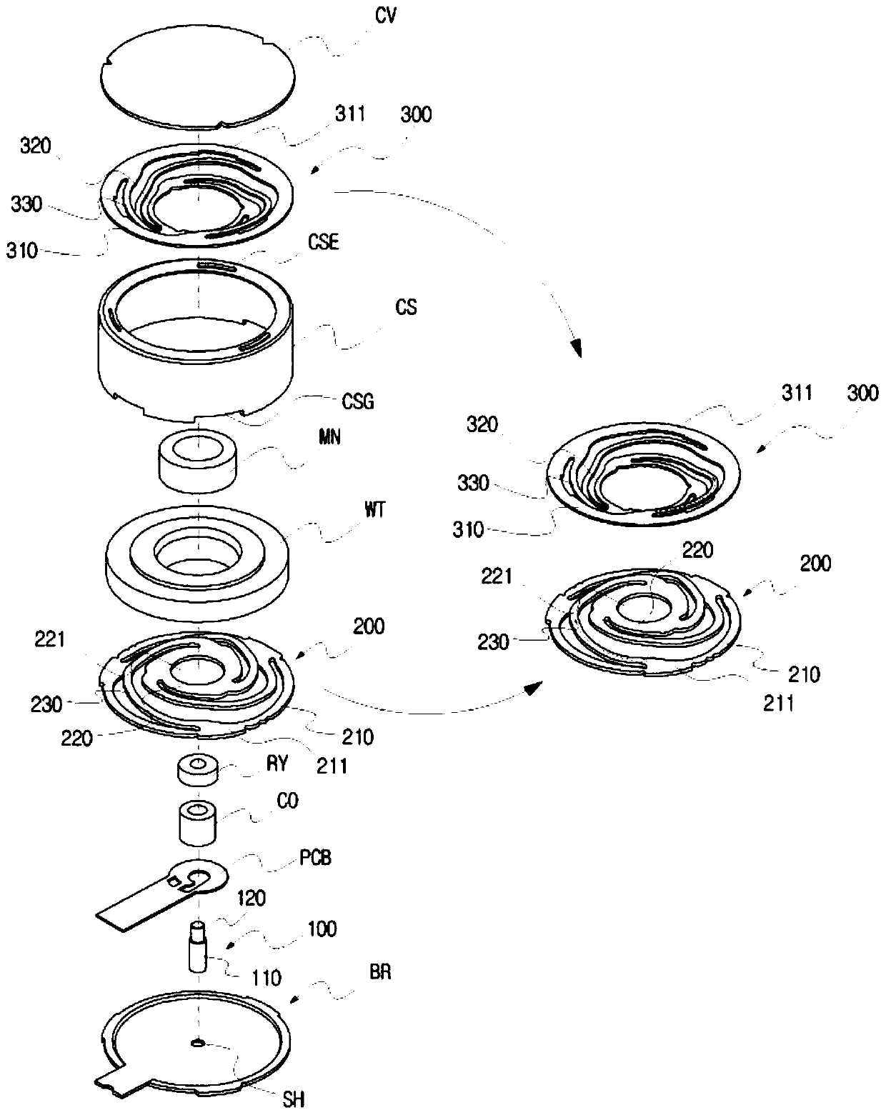
The invention relates to a linear vibration actuator. The linear vibration actuato comprises a bracket, a yoke shaft, a coil, a ring yoke, a bottom spring, a weight part, a top spring, and a top cover. The bottom spring is configured so that a bottom outer spring member having a ring shape and a bottom inner spring member having a coil through-hole formed in the center thereof protrude from bottom to top by a bottom bridging member having a spiral shape arranged in the counter-clockwise direction to form a whole; the outer peripheral edge part is provided with a fan-shaped position determining projection part which is combined with a fan-shaped position determining groove part that is correspondingly formed at the lower part of the housing part. The present invention relates to a vibration device capable of preventing the generation of partial vibration in the middle, reducing driving noise, and realizing long-term vibration by contactless vibration of a vibrating body.

Description


Claims


Application Information

Patent Timeline
Owner 天津富禄通信技术有限公司
Why Eureka
Try Eureka