Visible rack ceiling
A ceiling and panel technology, applied in the field of building materials, can solve the problems affecting the overall appearance of large ceilings, increase the difficulty of operation, etc., and achieve the effect of simple structure and low cost
- Summary
- Abstract
- Description
- Claims
- Application Information
AI Technical Summary
Benefits of technology
Problems solved by technology
Method used
Image

Examples
Embodiment 1
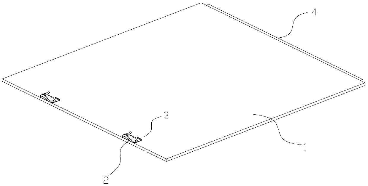
[0058] see Figure 1 to Figure 2, the embodiment of the present invention provides an exposed frame ceiling, including a panel 1, a storage sapwood 2 and a storage mechanism 3; the storage sapwood 2 is installed on the side edge of the panel 1, and the outside of the storage sapwood 2 is provided with a The mounted mounting part 5 is movably connected between the storage sapwood 2 and the side of the panel 1 through the storage mechanism 3, so that the storage sapwood 2 can be protruded or stored on the side of the panel 1.
[0059] The exposed frame ceiling of the present invention is different from the general ceiling structure in that the storage sapwood 2 used for erection can be arranged telescopically at the edge. When installation is required, the installer can first put away the storage sapwood 2 so that it will not interfere with the keel, and after the ceiling is supported above the keel, the installation worker can extend the storage sapwood 2 by operating the storage
Embodiment 2
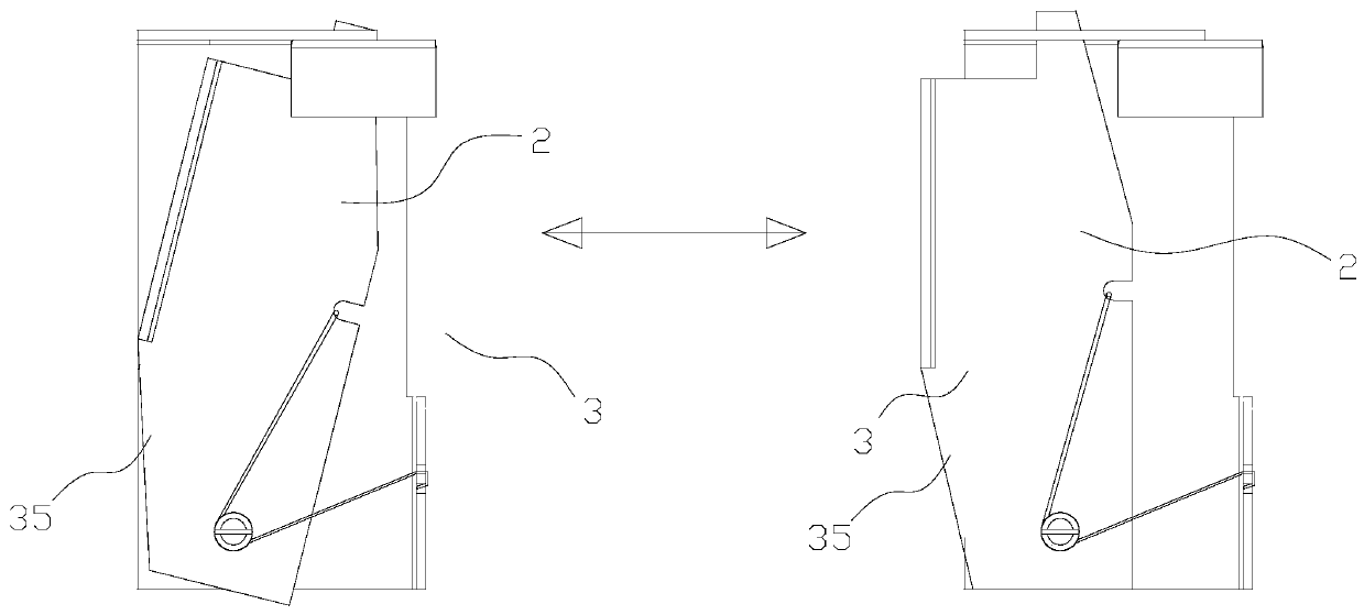
[0070] In this embodiment, the storage mechanism 3 still adopts the solution of swinging and ejecting, but the specific structure is different.
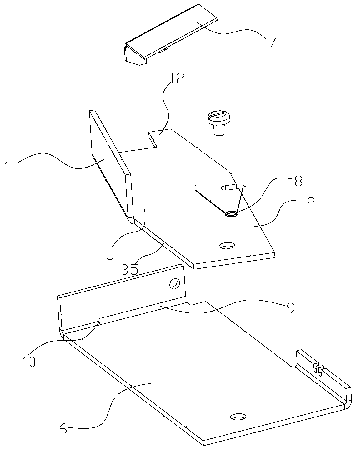
[0071] See 5 to Figure 8 In this embodiment, preferably, the storage mechanism 3 includes a base 6, a main shaft 14, a pressing shaft 15, a pressing spring 16 and a return spring 8; the base 6 is fixed on the side edge of the panel 1, and the main shaft 14 is vertically fixed on the On the base 6, the main shaft 14 is provided with a central hole 17 in the axial direction, and the base 6 is provided with a limit top edge 10 next to the main shaft 14, and one end for receiving the sapwood 2 is provided with a shaft hole 18 and passes through the shaft hole 18 and the main shaft 14. Rotation connection, and when the storage sapwood 2 rotates and pops up, it is set against the limit top edge 10; the main shaft 14 and the storage sapwood 2 are elastically connected by the return spring 8; the bottom end of the pressing shaft 15 is provided
Embodiment 3
[0077] In this embodiment, the storage mechanism 3 adopts a telescopic and pop-up scheme, and the storage sapwood 2 can be stretched and moved on the edge of the panel 1 .
[0078] see Figure 9 to Figure 12 , as preferably, the storage mechanism 3 includes a base 6, a return spring 8, a pressing block 21 and a pressing spring 16; the base 6 is fixed on the side edge of the panel 1, and the base 6 is provided with a horizontally arranged telescopic groove for accommodating the sapwood 2 It is slidingly connected with the telescopic groove; the storage sap material 2 and the base 6 are elastically connected by a return spring 8; a pressing spring 16 is provided between the bottom of the pressing block 21 and the base 6, and the pressing block 21 is provided with a lock for locking The locking catch 22, the bottom of the storage sapwood 2 is provided with a locking groove 23 that cooperates with the locking catch 22, so that the storage sapwood 2 is clamped in the locking groove 23
PUM
 Abstract
Description
Claims
Application Information
 - R&D Engineer
- R&D Manager
- IP Professional
- Industry Leading Data Capabilities
- Powerful AI technology
- Patent DNA Extraction
Browse by: Latest US Patents, China's latest patents, Technical Efficacy Thesaurus, Application Domain, Technology Topic.
© 2024 PatSnap. All rights reserved.Legal|Privacy policy|Modern Slavery Act Transparency Statement|Sitemap