Method for monitoring fluctuation of MOSFET gate line end cutting process

A cutting process and gate line technology, applied in the field of monitoring the fluctuation of MOSFET gate line end cutting process, can solve the problem of not representing the uniformity of on-chip feature size, increasing measurement time and equipment investment, affecting authenticity and accuracy, etc. problems, to achieve the effect of improving product yield, avoiding measurement impact, and saving time and cost

Inactive Publication Date: 2019-11-22
SHANGHAI HUALI INTEGRATED CIRCUTE MFG CO LTD
View PDF9 Cites 0 Cited by
  • Summary
  • Abstract
  • Description
  • Claims
  • Application Information

AI Technical Summary

Problems solved by technology

However, the bombardment of the electron beam will cause the deformation of the photoresist pattern, which will affect the authenticity and accuracy of the measurement results of the feature size line width
The measurement of key dimensions in mass production usually only measures 9 to 13 repeating units instead of all repeating units. The positions are scattered and the sampling is small, which cannot represent the uniformity of the feature size in the chi

Method used


Image

  • Method for monitoring fluctuation of MOSFET gate line end cutting process
  • Method for monitoring fluctuation of MOSFET gate line end cutting process
  • Method for monitoring fluctuation of MOSFET gate line end cutting process

Examples


Embodiment Construction

[0013] The method for monitoring the fluctuation of the MOSFET gate line end cutting process, in the following embodiments, taking a typical 28nm Poly-SiON (polysilicon gate-silicon oxynitride dielectric) MOSFET as an example, the specific implementation process is as follows:

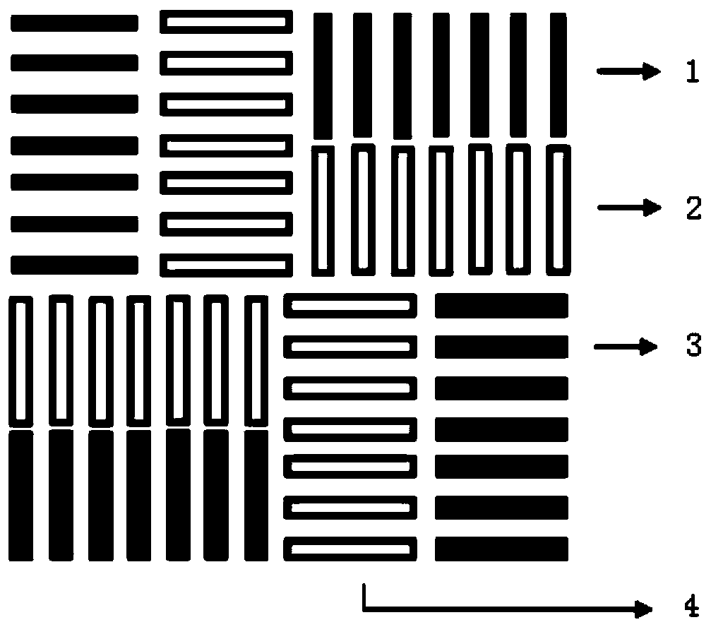
[0014] Step 1. Combine figure 1 As shown, the overlay pattern of the front layer grid is made, and the pattern is composed of a plurality of regularly arranged linear strips, and is arranged on the periphery of the entire overlay mark. The overlay pattern of the front grid is in the shape of a windmill. The gate overlay pattern on the front layer can also be composed of a plurality of grid bars, the length of the grid bars is 2-10 μm, the width is 0.5-2 μm, and the distance between the grid bars is 0.5-2 μm.

[0015] Step two, combine figure 1 As shown in the figure, the overlay pattern is made when the gate line end of the layer is cut. The pattern is composed of a plurality of regularly arranged long


PUM

PropertyMeasurementUnit
Lengthaaaaaaaaaa
Widthaaaaaaaaaa

Abstract

The invention discloses a method for monitoring fluctuation of a MOSFET gate line end cutting process. The method comprises the steps: 1, manufacturing a front-layer gate overlay pattern, and enablingthe gate overlay pattern to be arranged at the periphery of a whole overlay mark; 2, manufacturing a current gate line end cutting layer overlay pattern which is arranged on the inner side of the whole overlay mark; and 3, measuring an overlay precision value and a characteristic size value, and respectively correcting the overlay deviation of the gate cutting layer and the inner distribution ofan exposure energy sheet. The method can improve the feedback speed of the exposure condition, improves the efficiency, and reduces the cost.

Description


Claims


Application Information

Patent Timeline
Owner SHANGHAI HUALI INTEGRATED CIRCUTE MFG CO LTD
Why Eureka
Try Eureka