Fan control method, system and equipment and medium

A fan control and fan controller technology, which is applied in the server field, can solve the problems of fan burnout, burnout circuit, and protection circuit Mosfet+FUSE circuit burnout, etc., to achieve the effect of free manual maintenance and prevention of fan burning.

Pending Publication Date: 2022-05-13
SUZHOU LANGCHAO INTELLIGENT TECH CO LTD
View PDF0 Cites 0 Cited by
  • Summary
  • Abstract
  • Description
  • Claims
  • Application Information

AI Technical Summary

Problems solved by technology

[0003] Most of the existing DC fan protection schemes are to add a current impact protection circuit at the front of the DC fan. The damage of most DC fans is not directly caused by one-time overvoltage or overcurrent, but the fan speed is out of control due to unknown interference and other factors. , this state will keep rotating at high speed and full speed until the fan is short-circuited and burned
When the fan is short-circuited, it will cause the Mosfet+FUSE circui

Method used


Image

  • Fan control method, system and equipment and medium
  • Fan control method, system and equipment and medium
  • Fan control method, system and equipment and medium

Examples


Embodiment Construction

[0041] In order to make the object, technical solution and advantages of the present invention clearer, the embodiments of the present invention will be further described in detail below in conjunction with specific embodiments and with reference to the accompanying drawings.

[0042] It should be noted that all expressions using "first" and "second" in the embodiments of the present invention are to distinguish two entities with the same name but different parameters or parameters that are not the same, see "first" and "second" It is only for the convenience of expression, and should not be construed as a limitation on the embodiments of the present invention, which will not be described one by one in the subsequent embodiments.

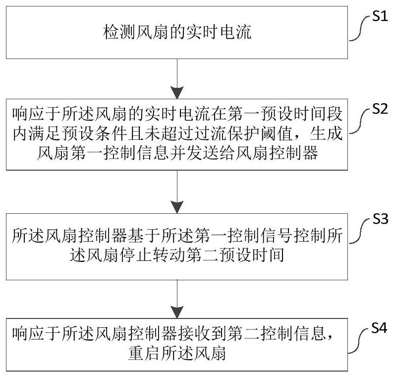
[0043] According to one aspect of the present invention, an embodiment of the present invention proposes a fan control method, such as figure 1 As shown, it may include the steps of:

[0044] S1, detect the real-time current of the fan;

[0045] S2,


PUM


Abstract

The invention discloses a fan control method. The fan control method comprises the following steps that the real-time current of a fan is detected; responding to the condition that the real-time current of the fan meets a preset condition in a first preset time period and does not exceed an overcurrent protection threshold value, generating fan first control information and sending the fan first control information to a fan controller; the fan controller controls the fan to stop rotating for a second preset time based on the first control signal; and responding to the second control information received by the fan controller, and restarting the fan. The invention further discloses a system, computer equipment and a readable storage medium. According to the scheme provided by the invention, the technical purposes of preventing the fan from being burnt when the fan is out of control and preventing relevant protection circuits of the MOSFET and the FUSE can be achieved, and fan fault isolation and fan fault self-repair can be automatically achieved without manual maintenance.

Description


Claims


Application Information

Patent Timeline
Owner SUZHOU LANGCHAO INTELLIGENT TECH CO LTD
Why Eureka
Try Eureka