Apparatus and method for treating electroplating plant area sewage

A sewage treatment device and plant area technology, applied in the direction of water/sewage treatment, water/sewage treatment equipment, water/sewage multi-stage treatment, etc., can solve the problem that the sewage treatment method cannot meet the sewage discharge standard, and achieve easy disassembly and replacement, reasonable structural design and simple operation

Inactive Publication Date: 2019-12-17
杨海琴
View PDF0 Cites 0 Cited by
  • Summary
  • Abstract
  • Description
  • Claims
  • Application Information

AI Technical Summary

Benefits of technology

This patented technology allows wastewater treatment plants to efficiently separate solids from liquor during its production process without causing damage or pollution. By adding an agitator inside the settling tanks, it helps break up any solid particles before they enter the system. Once mixed together, this mixture becomes more pure liquid instead of sludge. A special filter removes impurities like oil out of solution while allowing usable clarified fluid backflows towards the plant's main filtrations unit (FFU). Pumps move fluids around within them, create turbulence, and help make better separation between different types of materials. Overall, these technical improvements enhance the efficiency and effectiveness of wastewater processing systems.

Problems solved by technology

The technical issue addressed by this patented solution for treating wastewater from an industrial facility involves improving its efficiency during production processes without causing environmental pollution or damaging other equipment.

Method used


Image

  • Apparatus and method for treating electroplating plant area sewage
  • Apparatus and method for treating electroplating plant area sewage

Examples


Embodiment Construction

[0015] The following will clearly and completely describe the technical solutions in the embodiments of the present invention with reference to the accompanying drawings in the embodiments of the present invention. Obviously, the described embodiments are only some, not all, embodiments of the present invention.

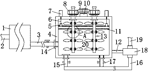
[0016] refer to Figure 1-2 , the electroplating plant sewage treatment device, including a sedimentation tank 1, the sedimentation tank 1 is provided with a sedimentation chamber, the side wall of the sedimentation tank 1 is provided with a first connecting pipe 2 communicating with the sedimentation chamber, and the sedimentation tank 1 is far away from the first connection The side wall at one end of the pipe 2 is penetrated with a second connecting pipe 3 communicating with the sedimentation chamber, and the side wall at one end of the second connecting pipe 3 far away from the sedimentation tank 1 is connected with a stirring tank 4, and the inside of the stirring t


PUM


Abstract

The invention discloses an apparatus and method for treating electroplating plant area sewage. The apparatus comprises a settling box, a settling cavity is arranged in the settling box, a first connecting tube intercommunicated with the settling cavity penetrates through the sidewall of the settling box, a second connecting tube intercommunicated with the settling cavity penetrates through the sidewall of one end, away from the first connecting tube, of the settling box, the sidewall of one end, away from the settling box, of the second connecting tube is connected with a stirring box, a stirring cavity is arranged in the stirring box, the second connecting tube penetrates through the sidewall of the stirring box and extends into the stirring cavity, two stirring rods penetrate through thesidewall of the upper end of the stirring box, the lower ends of the two stirring rods penetrate through the sidewall of the upper end of the stirring box and extend into the stirring cavity, and theouter sidewalls of sections, located in the stirring cavity, of the two stirring rods are provided with a plurality of fixing devices. The apparatus has the advantages of reasonable structural design, simplicity in operation, and ensuring of normal discharge of treated sewage by sufficiently treating the sewage.

Description


Claims


Application Information

Patent Timeline
Owner 杨海琴
Why Eureka
Try Eureka