Isolated gas lift drainage method

A gas-lift drainage and isolation technology, which is used in earth-moving drilling, sealing/packing, and fluid production. It can solve the problems of multiple downholes, complex processes, distance errors, etc., and achieve precise installation position control and simple process steps. Effect

Active Publication Date: 2019-12-31
PETROCHINA CO LTD +1
View PDF4 Cites 0 Cited by
  • Summary
  • Abstract
  • Description
  • Claims
  • Application Information

AI Technical Summary

Problems solved by technology

There are two main problems in this installation process: firstly, multiple downhole operations are required, the process is complicated and the cost is high; secondly, every re-downhole ope

Method used


Image

  • Isolated gas lift drainage method
  • Isolated gas lift drainage method
  • Isolated gas lift drainage method

Examples


Embodiment Construction

[0044] The present invention will be further described below in conjunction with the accompanying drawings, but the protection scope of the present invention is not limited to the following description.

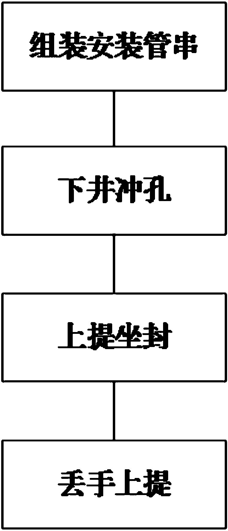
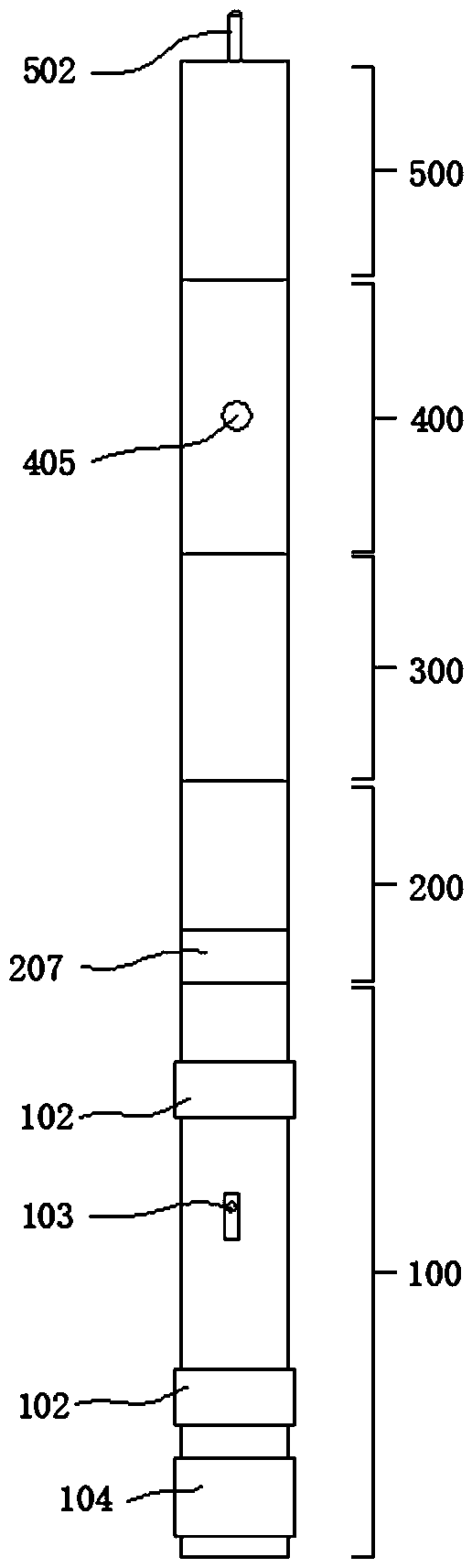
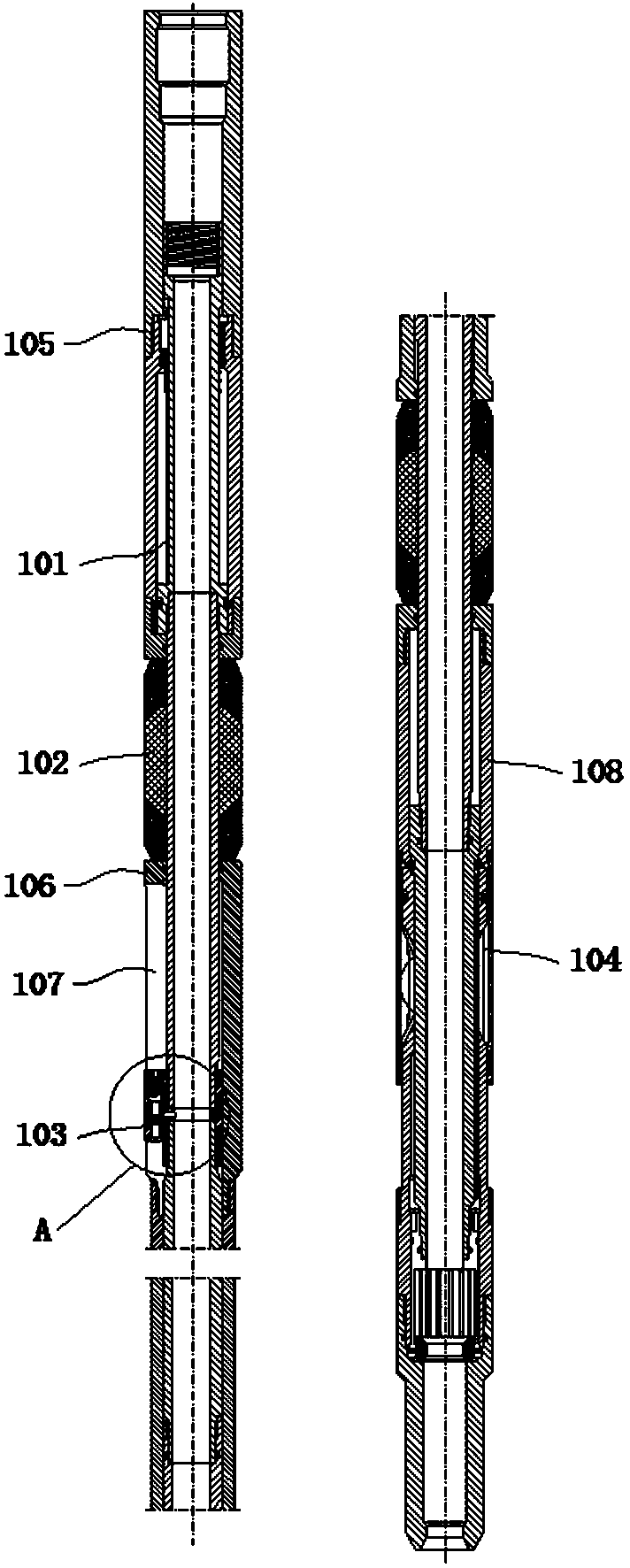
[0045] like figure 1 and figure 2 As shown, in an isolated gas lift drainage method of the present invention, the isolated gas lift drainage gas production pipe string is used to remove the liquid accumulation in the well, reduce the pressure of the liquid accumulation, and restore the production of the gas well. The isolated gas lift drainage gas production pipe string includes Isolated gas lift packer, setting tool, activation device and punching gun, including the following steps:

[0046] S1. Assembling and installing the pipe string; first, connect the first starting device, the punching gun 400, the second starting device and the isolated gas lift packer 100 in sequence, and the second starting device and the isolated gas lift packer 100 are connected by throwing Hand s


PUM


Abstract

The invention relates to an isolated gas lift drainage method. The isolated gas lift drainage method comprises the following steps: S1, a mounting pipe string is assembled, specifically, a first starting device, a punching gun (400), a second starting device and an isolated gas lift packer (100) are sequentially connected; S2, well lowering and punching are conducted, specifically, the mounting pipe string is lowered into the specified position from a production well pipe, and the first starting device controls the punching gun (400) to implement punching on the production well pipe; S3, upward lifting and setting are conducted, specifically, the mounting pipe string is upwards lifted, the isolated gas lift packer (100) is upwards moved to the punching position, and the second starting device controls the isolated gas lift packer (100) to conduct setting; S4, release and upward lifting are conducted, specifically, after setting, release is achieved, and the first starting device, the punching gun (400) and the second starting device are recovered to complete mounting; and S5, gas filling for liquid discharging is conducted, specifically, high-pressure gas is filled to discharge accumulated liquid. The mounting pipe string only needs to be lowered once, punching and setting are sequentially implemented, then the remaining mounting pipe string is lifted out, then mounting can becompleted, the process steps are simple, and mounting position control is more accurate.

Description


Claims


Application Information

Patent Timeline
Owner PETROCHINA CO LTD
Why Eureka
Try Eureka