Embedded laundry unit

A laundry machine and embedded technology, applied in the field of household products, can solve the problems of poor integrity, bulkiness, and unsightly appearance, and achieve the effect of strong integrity, simple structure, flat and concise structure

Pending Publication Date: 2020-01-14
ZHEJIANG BAOLAN ELECTRICAL IND
View PDF0 Cites 0 Cited by
  • Summary
  • Abstract
  • Description
  • Claims
  • Application Information

AI Technical Summary

Benefits of technology

This technology allows for easy installation without compromising any ornamental features like windows or doors. It uses special brackets attached to the wall's top edge with small openings at both ends. These brackets have an inner cavity containing shelf rails made up of metal wire mesh covered by plastic panels. Dryers used during this process hide these bars from view when they shouldn’t work properly. They may include different types of racks depending upon their placement within the room being cleaned. Additionally, there could be lift devices that allow multiple pairs of clothes to fit into each section of the system. Overall, it provides efficient use of space while ensuring safety and quality maintenance over longer periods of time.

Problems solved by technology

The technical problem addressed by this patented technology relates to finding ways to make clothes easier to dried during poor weathings without causing damage from exposures like sharp edges caused when inserting cutting tools into these hidden spaces inside the machine.

Method used


Image

  • Embedded laundry unit
  • Embedded laundry unit
  • Embedded laundry unit

Examples


Embodiment Construction

[0018] In order to make those skilled in the art more clearly understand the purpose, technical solutions and advantages of the present invention, the present invention will be further described below in conjunction with the accompanying drawings and embodiments.

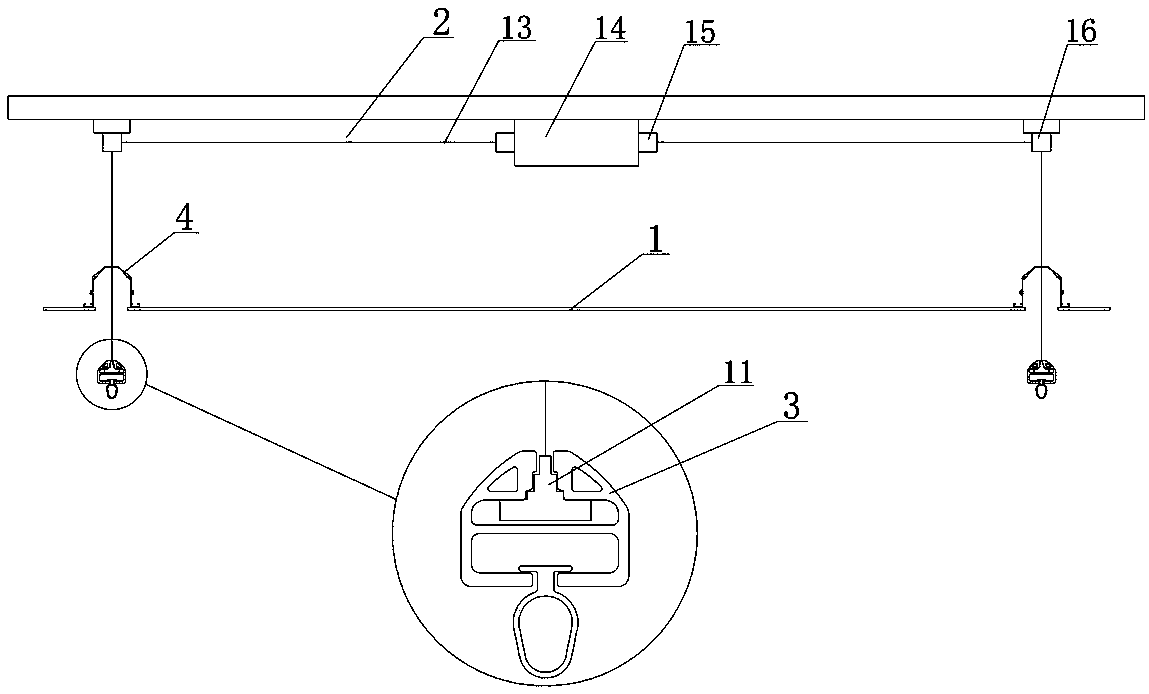
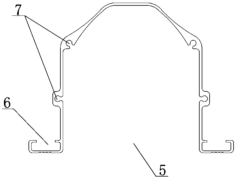
[0019] Such as Figure 1-3 As shown, an embedded clothes dryer according to the present invention includes a ceiling panel 1 and a clothes dryer body embedded in the ceiling panel 1, and the clothes dryer body includes a lifting device 2, a number of clothes rails 3 and The number of installation racks 4 is the same as that of the clothes-horse 3, and the clothes-horse 3 is connected below the installation rack 4 through a lifting device 2, and the lifting device 2 is used to drive the up or down of the clothes-horse 3 ; The mounting frame 4 is a strip-shaped structure with an opening at the bottom, the mounting frame 4 is provided with a concave cavity body 5 for accommodating the clothes-horse 3, and the bottom sides


PUM


Abstract

An embedded laundry unit comprises a ceiling panel and a laundry unit body embedded on the ceiling panel; the laundry unit body comprises a lifting device, a plurality of drying rods and mounting racks as many as the drying rods, and the drying rods are connected below the mounting racks through the lifting device; each mounting rack is of an elongated structure with an opening in the bottom, a concave cavity for accommodating one drying rod is arranged in each mounting rack, mounting grooves are formed outwardly in the two sides of the bottom of each mounting rack, and a plurality of edge-sealing screw mounting holes are uniformly formed in the concave cavity of each mounting rack; each drying rod comprises a shank and a clothes hanger pull ring arranged at the bottom of the shank, the top of each shank is provided with a stepped opening, a lifting wire-locking device matched with the stepped openings in size and shape is arranged in each stepped opening, the drying rods are connectedwith the lifting device through the lifting wire-locking device and can move up and down relative to the mounting racks, a clamping groove is formed in the bottom of each shank, and each clothes hanger pull ring is connected with the corresponding shank through one clamping groove.

Description


Claims


Application Information

Patent Timeline
Owner ZHEJIANG BAOLAN ELECTRICAL IND
Why Eureka
Try Eureka