Nonlinear system recognition method and equipment
A nonlinear system and identification method technology, applied in the field of nonlinear system identification methods and equipment, to achieve the effect of improving identification accuracy
- Summary
- Abstract
- Description
- Claims
- Application Information
AI Technical Summary
Benefits of technology
Problems solved by technology
Method used
Image

Examples
Embodiment 1
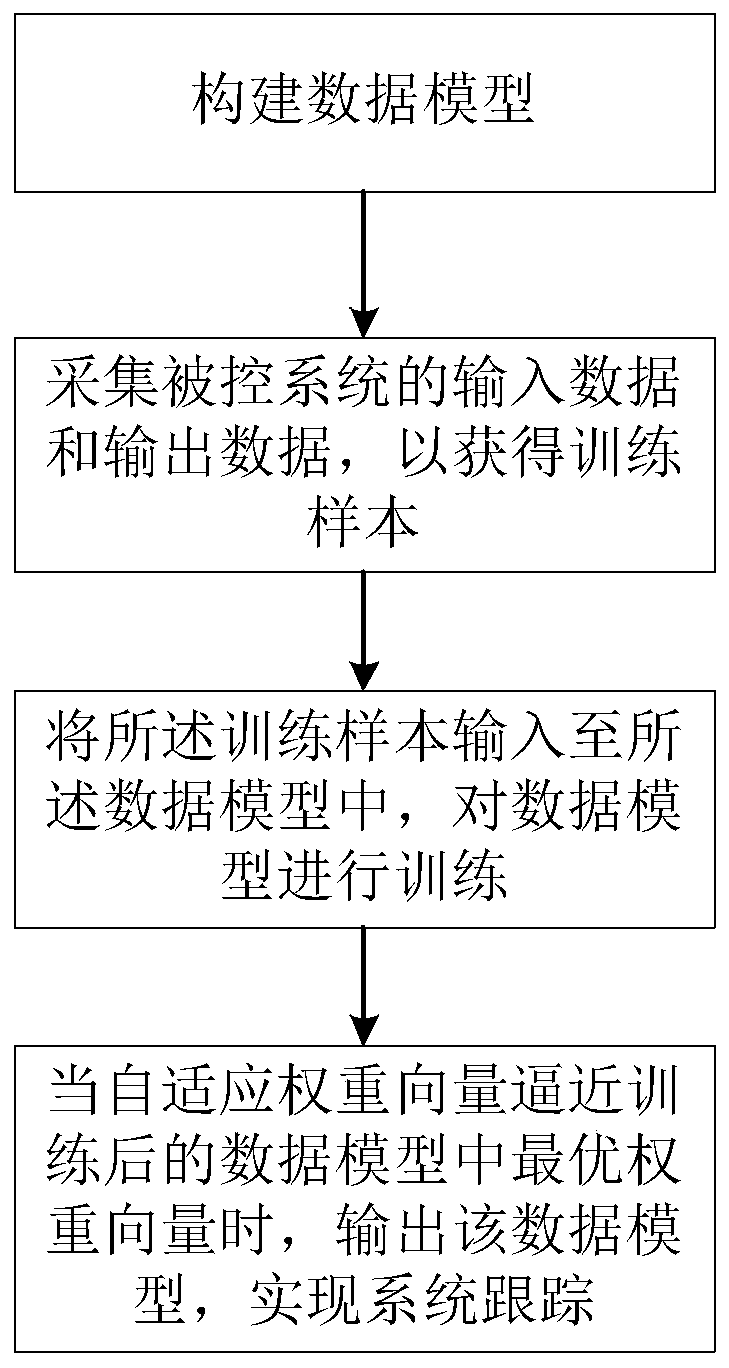
[0059] See figure 1 , The method as a whole includes risk sensitive loss (KRSL), Methods, k-means sampling and NysMKRSL-KM four parts.
[0060] (1) Kernel risk-sensitive loss criterion
[0061] Risk-sensitive loss is defined in the kernel space, which is called kernel risk-sensitive loss (KRSL). Two random variables X and Y are defined. KRSL is defined as follows:
[0062]
[0063] Here λ>0 is a risk-sensitive parameter, E is mathematical expectation, ‖·‖ is Euclidean norm, F XY (x,y) is the joint distribution function of (X,Y), and κ σ (·) represents a shift-constant kernel and bandwidth σ as follows:
[0064]
[0065] However, in practice, the joint distribution of X and Y is usually unknown. Therefore, the empirical KRSL is defined as follows:
[0066]
[0067] among them Indicates the limited number of samples available, and N is the sample size.
[0068] (2) method
[0069] Collect the input data and output data of the controlled system to obtain training samples; suppose the train
Embodiment 2
[0141] The second embodiment provides a nonlinear system identification device, see Figure 4 ,include:
[0142] Building unit: used to build the following data model: Among them, u is the zero mean Gaussian sequence of the input unit variance, z(u) is the vector that maps u to finite dimensions, Ω o Is the weight vector, v is the system interference noise; d is the desired signal;
[0143] Acquisition unit: used to collect input data and output data of the controlled system to obtain training samples;
[0144] Training unit: used to input the training samples into the data model to train the data model; when the adaptive weight vector Ω approaches the optimal weight vector Ω in the trained data model o When, output the data model to achieve system tracking.
[0145] For the brief description of the system provided in the embodiment of the present invention, for the parts not mentioned in the embodiment, please refer to the corresponding content in the foregoing method embodiment.
Embodiment 3
[0147] The third embodiment provides the application of the method and system on the basis of the foregoing embodiment.
[0148] System identification is now widely used in various fields.
[0149] For example, in the chemical industry, it can be used to control the diameter of electrospun fibers during processing. Since the electric charge on the surface of the electrospun fiber will affect the diameter of the electrospun fiber, but because its control relationship characteristics are unknown, and when the machine ages, its control relationship will also change, so the system identification can be applied to electrospinning In the field of fiber processing, the specific steps include: acquiring the input data and output data of the controlled system, that is, acquiring the electrical charge on the surface of the electrospun fiber and the corresponding diameter in the historical electrospun fiber processing data. Input the charge on the surface of the electrospun fiber and the corres
PUM
 Abstract
Description
Claims
Application Information
 - R&D Engineer
- R&D Manager
- IP Professional
- Industry Leading Data Capabilities
- Powerful AI technology
- Patent DNA Extraction
Browse by: Latest US Patents, China's latest patents, Technical Efficacy Thesaurus, Application Domain, Technology Topic.
© 2024 PatSnap. All rights reserved.Legal|Privacy policy|Modern Slavery Act Transparency Statement|Sitemap