Tail end executing mechanism and longitudinal bar conveying robot

A technology of end-execution and longitudinal reinforcement, which is applied in the field of end-effectors and longitudinal reinforcement delivery robots, can solve the problems of manual operation and low efficiency of steel cage manufacturing, and achieve the effect of improving manufacturing efficiency

Pending Publication Date: 2020-02-21
CHINA CONSTR SCI & TECH CO LTD
View PDF0 Cites 0 Cited by
  • Summary
  • Abstract
  • Description
  • Claims
  • Application Information

AI Technical Summary

Benefits of technology

This inventive device uses two different types of presses: an upper roller with teeth on its surface called primary pressure wheel, where there are holes near each other (longitudinally) to hold the ends of steel rods together when they are being worked during construction work. A lower roller has teeth on top to support these long strands while moving them towards the machine's center. When this happens, the force from both drums causes the rod to expand slightly beyond what was previously held tight against itself. To achieve this, the devices use motors to control their movements. By rotating the drum about multiple axes simultaneously, the length of the rod may go faster without getting stuck due to friction. These machines allow workers to perform various tasks more efficiently because they have less physical effort compared to traditional methods like screw-tightening bolts.

Problems solved by technology

The technical problem addressed in this patented text relates to manual assembly of steel bar reinforceings due to difficulties with attaching or removing these reinforcers during production processes. This can lead to lower productivity for companies that require large amounts of material compared to traditional methods such as welding bolts together.

Method used


Image

  • Tail end executing mechanism and longitudinal bar conveying robot
  • Tail end executing mechanism and longitudinal bar conveying robot
  • Tail end executing mechanism and longitudinal bar conveying robot

Examples


Embodiment Construction

[0040] Embodiments of the present invention are described in detail below, examples of which are shown in the drawings, wherein the same or similar reference numerals designate the same or similar elements or elements having the same or similar functions throughout. The embodiments described below by referring to the figures are exemplary and are intended to explain the present invention and should not be construed as limiting the present invention.

[0041] In describing the present invention, it should be understood that the terms "length", "width", "upper", "lower", "front", "rear", "left", "right", "vertical", The orientation or positional relationship indicated by "horizontal", "top", "bottom", "inner", "outer", etc. are based on the orientation or positional relationship shown in the drawings, and are only for the convenience of describing the present invention and simplifying the description, rather than Nothing indicating or implying that a referenced device or element mu


PUM


Abstract

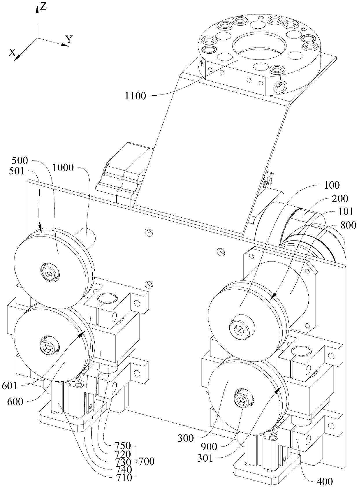
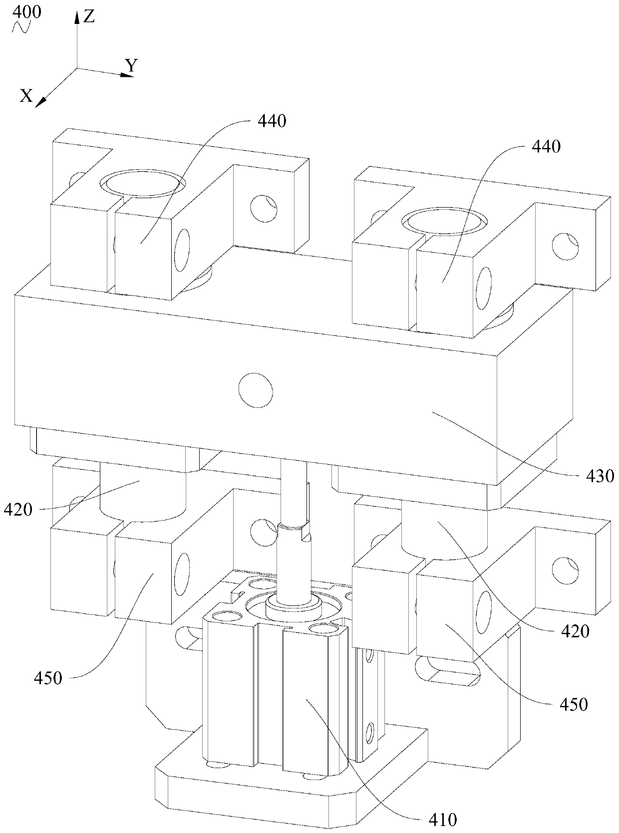
The invention relates to the technical field of reinforcement cage manufacturing, and provides a tail end executing mechanism and a longitudinal bar conveying robot. The tail end executing mechanism is used for clamping a longitudinal bar and enabling the longitudinal bar to pass through at least one stirrup. The tail end executing mechanism comprises a driving wheel, an active drive assembly, a main pressing wheel and a main pressing driving assembly. The active drive assembly is used for driving the driving wheel to do rotating motion around a first axis. The main pressing wheel is arrangedvertically opposite to the driving wheel. The main pressing driving assembly is used for driving the main pressing wheel to move up and down relative to the driving wheel. The outer wheel face of thedriving wheel and the outer wheel face of the main pressing wheel can be jointly used for clamping the longitudinal bar. The driving wheel can drive the longitudinal bar to move to the left or the right under the driving of the active drive assembly. The main pressing wheel can rotate around a second axis under the driving of the longitudinal bar. The first axis and the second axis are verticallyarranged relative to the left-right direction. The tail end executing mechanism not only can realize the clamping of the longitudinal bar, but also can enable the longitudinal bar to pass through theat least one stirrup quickly and smoothly so as to realize the operation of longitudinal bar penetration, so that the manufacturing efficiency of the reinforcement cage can be improved to a great extent.

Description


Claims


Application Information

Patent Timeline
Owner CHINA CONSTR SCI & TECH CO LTD
Why Eureka
Try Eureka