U-band microwave direct modulation system

A modulation system and frequency band technology, applied in the field of U-band microwave direct modulation system, to fill the domestic gap, solve the bottleneck problem, and achieve good carrier index.

Active Publication Date: 2020-02-21
XIAN INSTITUE OF SPACE RADIO TECH
View PDF8 Cites 3 Cited by
  • Summary
  • Abstract
  • Description
  • Claims
  • Application Information

AI Technical Summary

Problems solved by technology

[0007] The technical problem solved by the present invention is: to overcome the deficiencies of the prior art, to provide a U-band microwave direct modulation system, to directly

Method used


Image

  • U-band microwave direct modulation system
  • U-band microwave direct modulation system
  • U-band microwave direct modulation system

Examples


Embodiment Construction

[0054] The present invention will be further described in detail below in conjunction with the accompanying drawings and specific embodiments.

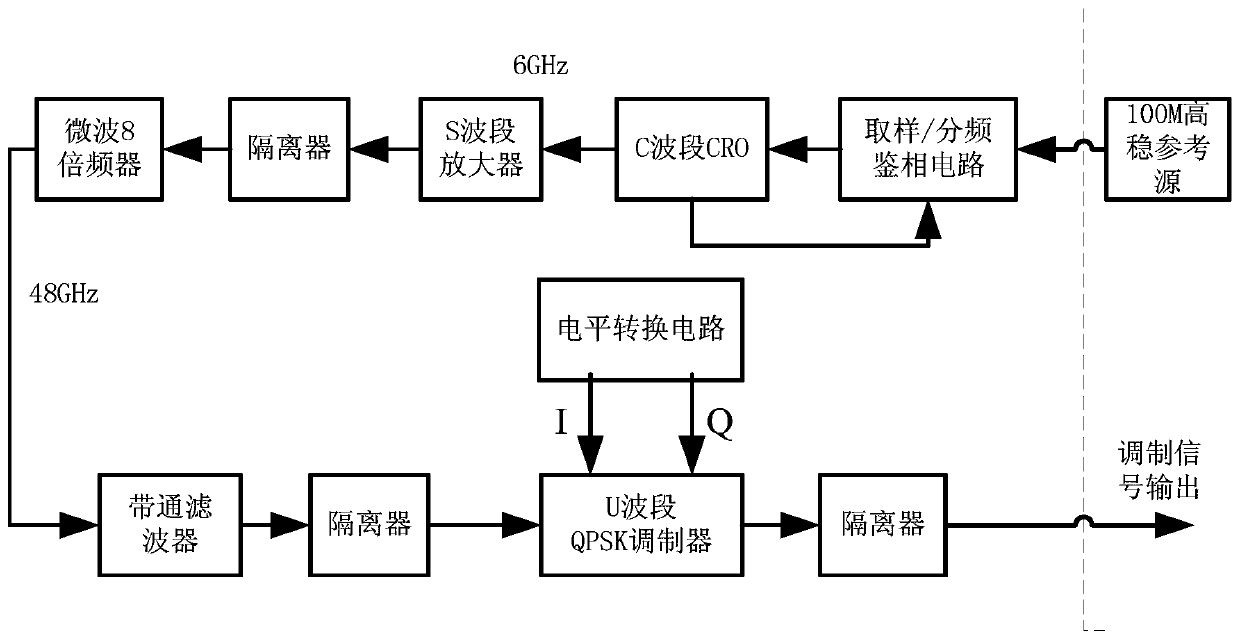
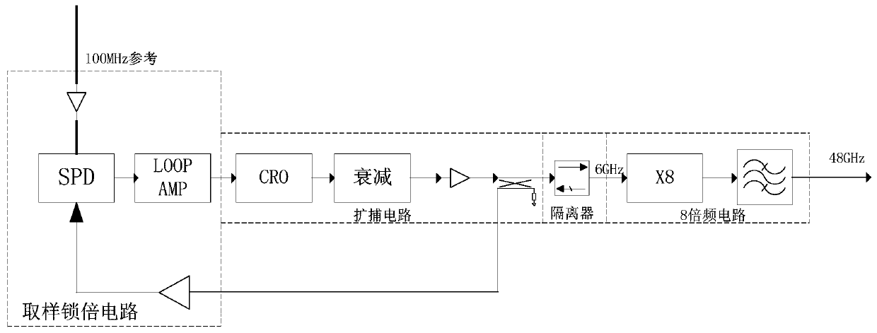
[0055] A U-band microwave direct modulation system of the present invention comprises: a C-band local oscillator circuit, a C-band amplifying circuit, a U-band 8-fold frequency circuit, a U-band QPSK microwave direct modulation circuit, and a level conversion circuit; a C-band local oscillator The circuit takes a high-stable reference source as input, performs sampling and phase-locking on the high-stable reference source, and generates a C-band carrier with extremely low phase noise; the C-band amplifier circuit performs power amplification and isolation on the C-band carrier with extremely low phase noise; The U-band 8-frequency multiplication circuit performs multiple harmonic multiplication and isolation on the amplified and isolated C-band carrier with extremely low phase noise, thereby generating a U-band carrier; the level conversi


PUM


Abstract

A U-band microwave direct modulation system comprises a C-band local oscillation circuit, a C-band amplification circuit, a U-band 8-frequency multiplication circuit, a U-band QPSK microwave direct modulation circuit and a level conversion circuit. The C-band local oscillator circuit takes a high-stability reference source as an input, performs sampling phase locking on the high-stability reference source, and generates C-band carrier waves with extremely low phase noise; the C-band amplifying circuit is used for carrying out power amplification and isolation on the C-band carrier with extremely low phase noise; the U-frequency band 8-frequency multiplication circuit is used for carrying out multiple harmonic frequency multiplication and isolation on the amplified and isolated C-frequencyband carrier wave with extremely low phase noise so as to generate a U-frequency band carrier wave; the level conversion circuit performs bipolar conversion on the external data to obtain bipolar level data; and the QPSK microwave direct modulation circuit of the U frequency band modulates the phase of the carrier of the U frequency band under the data driving of the bipolar level to realize QPSKmodulation so as to obtain a QPSK modulation signal, and the QPSK modulation signal is isolated and then output.

Description


Claims


Application Information

Patent Timeline
Owner XIAN INSTITUE OF SPACE RADIO TECH
Why Eureka
Try Eureka