Manufacturing method of vibration reduction road pad

A manufacturing method and stacking technology are applied in the manufacturing field of vibration damping pads for railway and urban track construction, which can solve the problems of high mold cost, inability to completely solve the problems of gas export and high mold design requirements, and achieve the effect of ensuring quality

Active Publication Date: 2020-03-24
北京思达维科技有限公司
View PDF10 Cites 1 Cited by
  • Summary
  • Abstract
  • Description
  • Claims
  • Application Information

AI Technical Summary

Problems solved by technology

It has a certain effect but cannot completely solve the problem of gas export, and the cost is high, and the mold design requirements are relatively high
The technical scheme of designing air guide grooves on the surface of the press mold has high requirements on the fl

Method used


Image

  • Manufacturing method of vibration reduction road pad
  • Manufacturing method of vibration reduction road pad
  • Manufacturing method of vibration reduction road pad

Examples


Embodiment Construction

[0023] In order to make the purpose, technical solution and advantages of the present invention clearer, the technical solution of the present invention will be further clearly and completely described below in conjunction with the embodiments of the present invention. It should be noted that the described embodiments are only some of the embodiments of the present invention, but not all of the embodiments. Based on the embodiments of the present invention, all other embodiments obtained by persons of ordinary skill in the art without making creative efforts belong to the protection scope of the present invention.

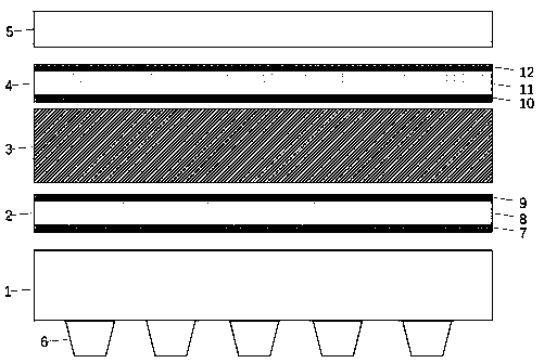
[0024] It should be understood that the orientation or positional relationship indicated by the terms "upper", "lower", "front", "rear", "left", "right" etc. are based on the orientation or positional relationship shown in the drawings, and are only In order to facilitate the description of the present invention and simplify the description, it does not indicate or im


PUM


Abstract

The invention discloses a manufacturing method of a vibration reduction road pad. A rubber stacking layer is formed by functional layers such as a damping layer, a first woven cloth lamination layer,an interlayer, a second woven cloth lamination layer and a covering layer, and hot-pressing vulcanization integrated forming is carried out. A hot-press forming mold is added into a vulcanizing press;the upper surface of the mold is in horizontal distribution and is provided with inverted cone-frustum-shaped through holes distributed in a matrix array; hot press molding treatment is performed onthe damping layer so as to form an array-shaped bulge structure on the surface of the damping layer, the gas flow guide layers are arranged between the rubber stacking layer and the upper flat plate and the lower flat plate of the vulcanizing press. The gas generated by the vulcanization process in the rubber vibration reduction road pad can be effectively guided to the outside, so that unexpectedbulges and pits are prevented from being formed on the inner and outer structures of the rubber vibration reduction road pad product due to the concentration of the gas area, and the quality of the vibration reduction road pad structure is effectively ensured.

Description


Claims


Application Information

Patent Timeline
Owner 北京思达维科技有限公司
Why Eureka
Try Eureka