Simulated installation method for three-cylinder crankshaft bearing of diaphragm pump

A technology for simulating installation and crankshaft bearings. It is applied in geometric CAD, computer-aided design, design optimization/simulation, etc. It can solve the problems of bearing and crankshaft installation stuck, unable to install, etc., to avoid stuck or unable to install.

Pending Publication Date: 2020-04-07
SHAANXI AEROSPACE POWER HIGH TECH
View PDF4 Cites 1 Cited by
  • Summary
  • Abstract
  • Description
  • Claims
  • Application Information

AI Technical Summary

Benefits of technology

This patented technology allows for simulations with an engine's cam shaft and bearings without requiring modifications made at the time they were designed. It uses computer graphics techniques to create images showing how different colors can appear depending upon which parts have been moved around within them. When this happens, if any patterns occur between these components, such as overlapping lines, the dimensions will become too big, causing damage. To prevent this issue, the design includes a special part called a dummy component attached to the image beforehand. By comparing the colored appearance of both the cam shaped object (cranking wheel) and its corresponding bearing counterpart, we may determine if there has some problem with fitting either correctly into place.

Problems solved by technology

This patented technical problem addressed in this patents relates to improving the performance of bearings during use in reciprocation type hydraulic systems such as those described earlier. Lubricants are commonly applied to connect rods between different parts within these systems due to their importance in reducing wear caused by repeated movement over time. However, current methods require excessive machining processes at both ends of each connection portion, making them hard-to maintain properly.

Method used


Image

  • Simulated installation method for three-cylinder crankshaft bearing of diaphragm pump
  • Simulated installation method for three-cylinder crankshaft bearing of diaphragm pump
  • Simulated installation method for three-cylinder crankshaft bearing of diaphragm pump

Examples


Embodiment 1

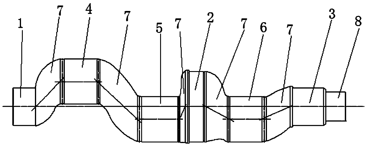
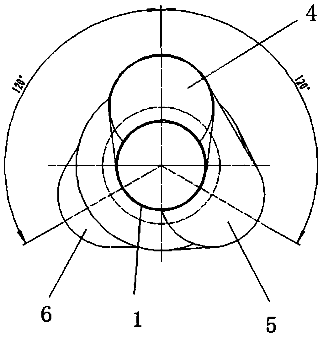
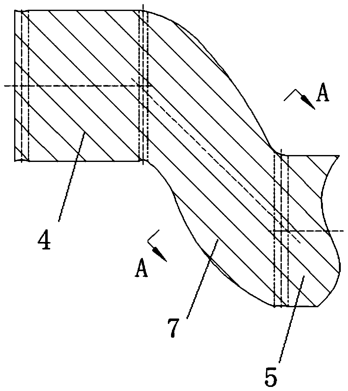
[0072] Such as Figure 1 to Figure 16 As shown, a simulated installation method of a three-cylinder crankshaft bearing of a diaphragm pump includes the following steps:

[0073] 1) Drawing software to draw 3D model

[0074] 1.1) design the crankshaft, and draw the crankshaft 9 three-dimensional models in the drawing software, and set it to an opaque state, and the color is set as the first light color; wherein, the drawing software is solidworks; the inner surface of the three-dimensional bearing simulation ring 10 is a conical surface, The taper of the cone surface is 1:12.

[0075] 1.2) Draw a three-dimensional bearing simulation ring 10, whose structural size is the same as that of the bearing to be installed, and the inner surface of the three-dimensional bearing simulation ring 10 is a conical surface; and set it to a light-colored translucent state, and set the color to the second light color; After the first light color and the second light color are clearly distinguishe

Embodiment 2

[0088] Such as Figure 17 to Figure 19 As shown, a simulated installation method of a three-cylinder crankshaft bearing of a diaphragm pump includes the following steps:

[0089] 1) Drawing software to draw two-dimensional model

[0090] 1.1) Design the crankshaft, and draw multiple contours of the crankshaft at different rotation angles according to the design size, and set each contour as a thick solid line;

[0091] 1.2) Draw a two-dimensional bearing simulation ring 10, whose outline size is the same as that of the bearing to be installed, and set it as a dotted line; the thick solid line and the dotted line are clearly distinguished, and a linear intersection 11 appears after overlapping;

[0092] 2) Simulated installation of bearings

[0093] Each profile of the crankshaft 9 and the two-dimensional bearing simulation ring 10 are displayed on the screen, so that the two-dimensional bearing simulation ring 10 passes through the crankshaft 9 from one end of the crankshaft 9


PUM

PropertyMeasurementUnit
Tensile strengthaaaaaaaaaa
Yield strengthaaaaaaaaaa

Abstract

The invention provides a simulated installation method for a three-cylinder crankshaft bearing of a diaphragm pump so that the problem that an existing bearing and a crankshaft are clamped or cannot be installed is solved. The method comprises the following steps: 1.1) designing a crankshaft, drawing a crankshaft three-dimensional model in drawing software, setting the crankshaft three-dimensionalmodel to be in an opaque state, and setting the crankshaft three-dimensional model to be in a first light color; 1.2) drawing a three-dimensional bearing simulation ring of which the structural sizeis the same as that of the to-be-mounted bearing, setting the three-dimensional bearing simulation ring to be in a light-color semitransparent state, and setting the three-dimensional bearing simulation ring to be in a second light color; wherein the first light color and the second light color are obviously distinguished and are displayed as a dark color or an opaque color after being overlapped;2) displaying the crankshaft three-dimensional model and the three-dimensional bearing simulation ring on a screen, and enabling the bearing simulation ring to penetrate through the crankshaft from one end of the crankshaft and reach a mounting position; if the two colors are not changed when the crankshaft passes through, the currently designed crankshaft meets the requirement; and if dark-coloror opaque patterns are observed during penetration, indicating that the currently designed crankshaft does not meet the requirements, requiring redesign, and executing the step 1) again until the designed crankshaft meets the requirements.

Description


Claims


Application Information

Patent Timeline
Owner SHAANXI AEROSPACE POWER HIGH TECH
Why Eureka
Try Eureka