Electric back door unlocking control method and electric back door lock
A control method and unlocking technology, applied in electric locks, electrical locking circuits, building locks, etc., can solve problems such as vehicle water ingress safety, and achieve the effect of ensuring manual operation time requirements
- Summary
- Abstract
- Description
- Claims
- Application Information
AI Technical Summary
Problems solved by technology
Method used
Image

Examples
Embodiment 1
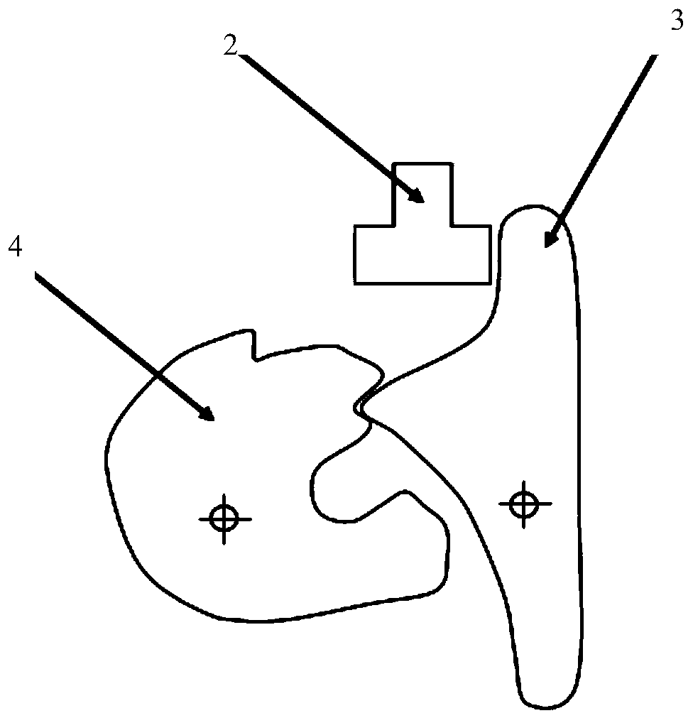
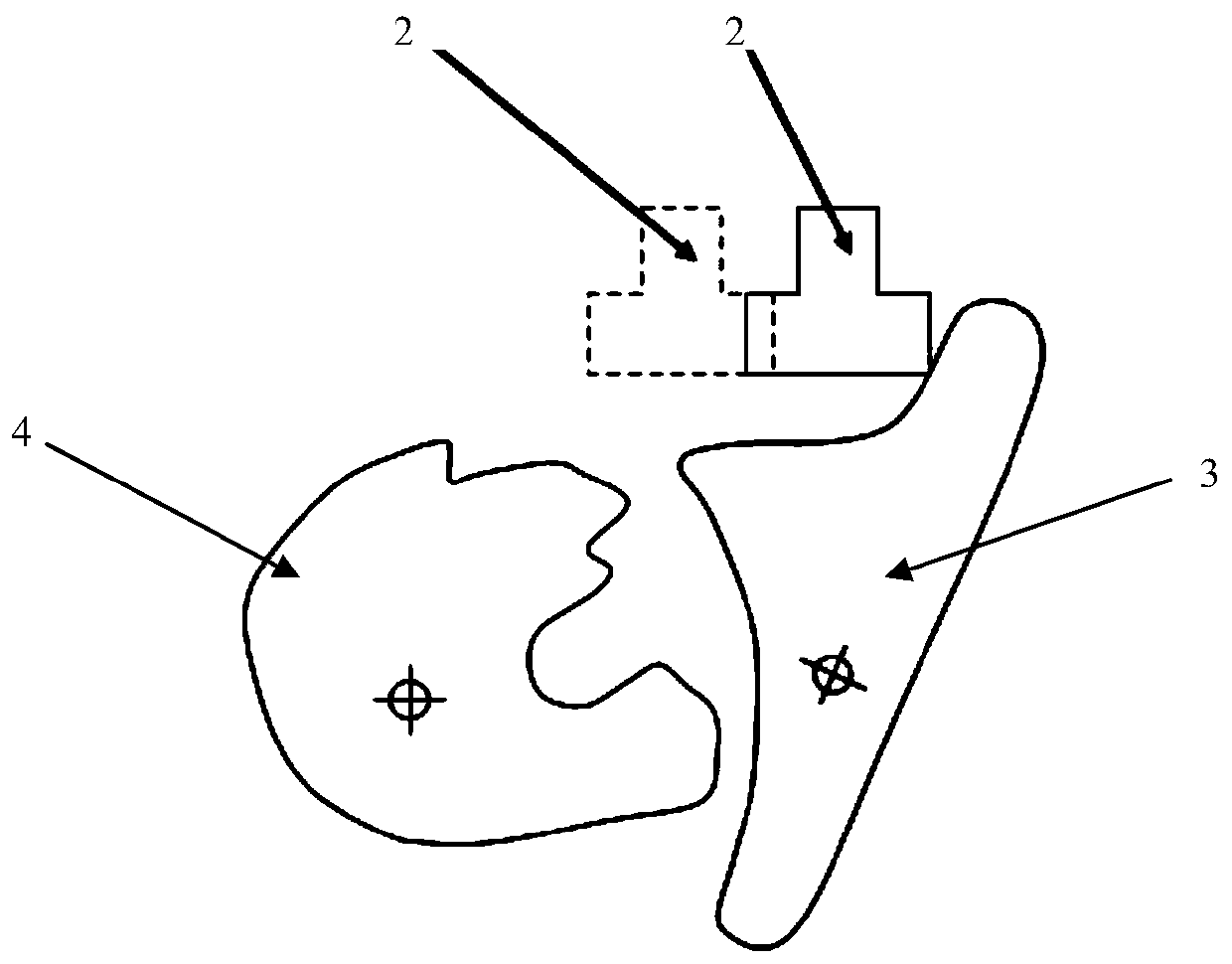
[0061] Such as Figure 2-7 As shown, the electric back door lock includes a door lock motor, an unlocking link 2, a pawl 3 and a ratchet 4. When the door lock motor rotates in the forward direction, the unlocking link 2 is driven to push the pawl 3, so that the pawl 3 releases the ratchet 4. When the door lock motor rotates in the reverse direction, the unlocking link 2 is reset, and the pawl 3 is reset under the action of the return spring;
[0062] Also includes a control unit 5, the control unit includes a first timer 51, a first detector 52 and a second timer 53;
[0063] The control unit 5 is used to send an unlock signal to the door lock motor, and the door lock motor rotates forward after receiving the unlock signal;
[0064] The first timer 51 is used to start timing after the unlocking link 2 is in the release position;
[0065] The first detector 52 is used to detect the ratchet half-lock position signal when the first timer 51 starts counting;
[0066] When the firs
Embodiment 2
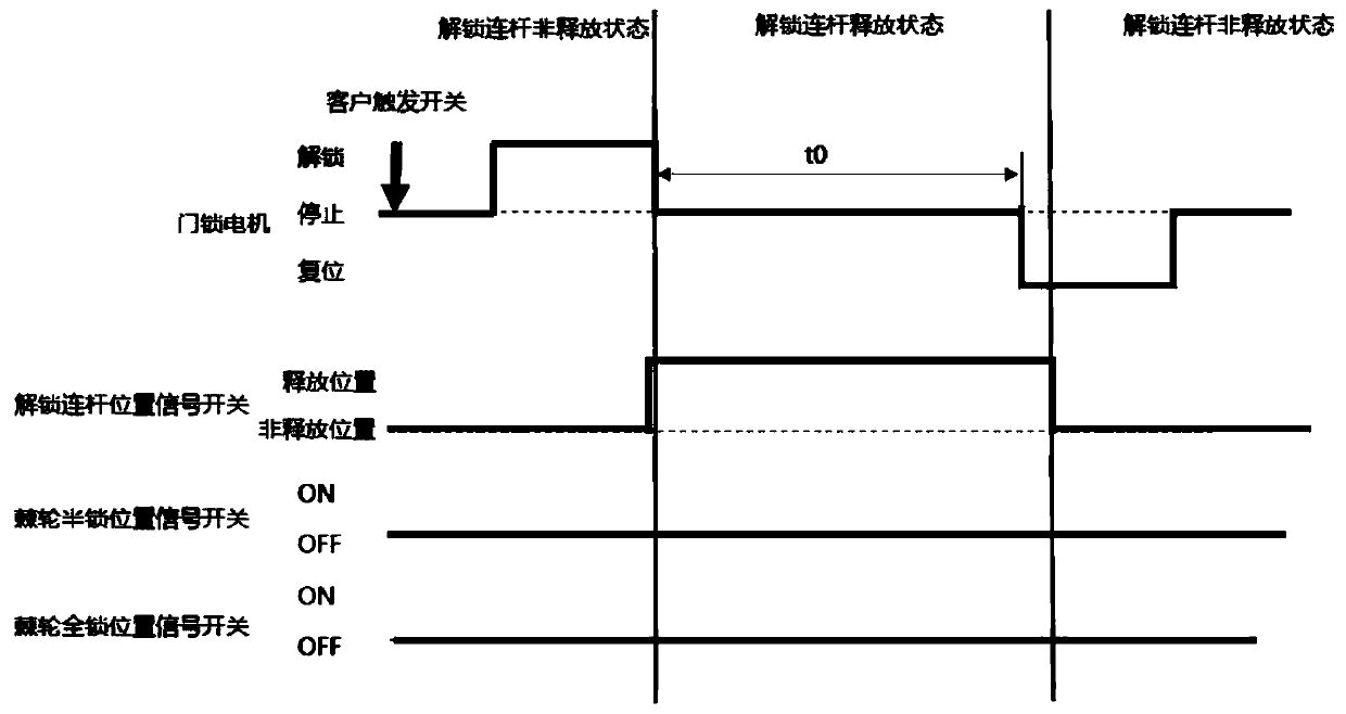
[0087] Such as Figure 8 As shown, the electric back door unlocking control method includes the following steps:
[0088] Drive the door lock motor so that the unlocking link 2 is in the release position;
[0089] Wherein, the door lock motor may be driven by a user triggering a door lock switch.
[0090] Set the first set time period t1 and start timing, and simultaneously detect the ratchet half-lock position signal;
[0091] Before the end of the first set time period t1, when it is detected that the ratchet half-lock position signal jumps,
[0092] Terminate the timing of the first set time period t1, set the second set time period t2 and start timing,
[0093] After the second set time period t2 ends, the door lock motor is driven to reset, and the unlocking link 2 is reset under the action of the return spring;
[0094] When the first set time period t1 ends, the ratchet half-lock position signal does not jump, and the door lock motor is driven to reset, and the unlocki
Embodiment 3
[0104] Such as Figure 9 As shown in , when the back door is normally electrically opened, the door lock motor is driven to make the unlocking link 2 in the release position;
[0105] Start timing and simultaneously detect the position signal of the ratchet half lock;
[0106] Before the end of the first set time period t1, when it is detected that the ratchet half-lock position signal jumps, the timing of the first set time period t1 is terminated, and the second set time period t2 is started, and the second setting After the time period t2 ends, the door lock motor is driven to reset, and the unlocking link 2 is reset under the action of the reset spring.
[0107] In this working condition, the half-lock position signal switch jumps within the first set time period t1, the first timer 51 is stopped, the second timer 53 is started, and reset after 500 ms. At this time, after the system is unlocked, it only needs to wait for 500ms to fully support the next door lock operation.
PUM
 Abstract
Description
Claims
Application Information
 - R&D Engineer
- R&D Manager
- IP Professional
- Industry Leading Data Capabilities
- Powerful AI technology
- Patent DNA Extraction
Browse by: Latest US Patents, China's latest patents, Technical Efficacy Thesaurus, Application Domain, Technology Topic.
© 2024 PatSnap. All rights reserved.Legal|Privacy policy|Modern Slavery Act Transparency Statement|Sitemap