Magnetic induction through-the-earth positioning method based on path loss

A technology of path loss and positioning method, applied in positioning, measuring devices, instruments, etc., can solve problems such as positioning error and dielectric loss, and achieve the effect of reducing loss and accurately positioning through the ground

Active Publication Date: 2020-06-02
BEIJING JIAOTONG UNIV
View PDF5 Cites 4 Cited by
  • Summary
  • Abstract
  • Description
  • Claims
  • Application Information

AI Technical Summary

Problems solved by technology

This method can achieve horizontal positioning and vertical positioning, but the dielectric loss will occur when the magnetic

Method used


Image

  • Magnetic induction through-the-earth positioning method based on path loss
  • Magnetic induction through-the-earth positioning method based on path loss
  • Magnetic induction through-the-earth positioning method based on path loss

Examples


Embodiment 1

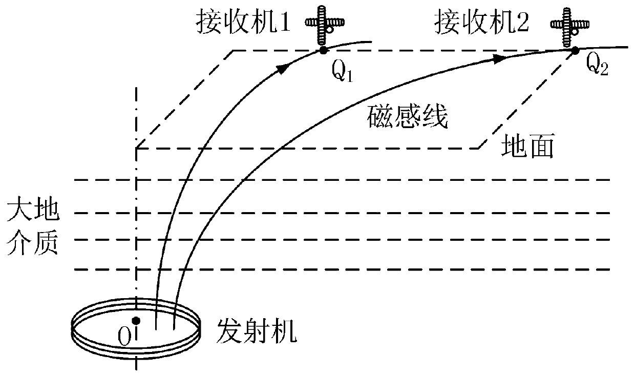
[0050] Embodiment 1 of the present invention provides a magnetic induction penetrating ground positioning method based on path loss. In the embodiment of the present invention, the transmitter of the system is a single-axis annular energized coil placed horizontally underground. The receiver is a three-axis orthogonal induction magnetic core coil placed on the ground, one axis of the coil is perpendicular to the horizontal ground, and the other two axes are parallel to the horizontal ground. There is a conductive earth medium between the transceivers. There is a sinusoidal current of a certain frequency (such as 10Hz) in the multi-turn coil of the transmitter. The quasi-static magnetic field excited by the current passes through the earth medium to the receiver on the ground, and is respectively at the two ends of the three magnetic core coils of the receiver. The induced voltage signal is generated, and the direction and intensity of the magnetic induction penetrating positionin

Embodiment 2

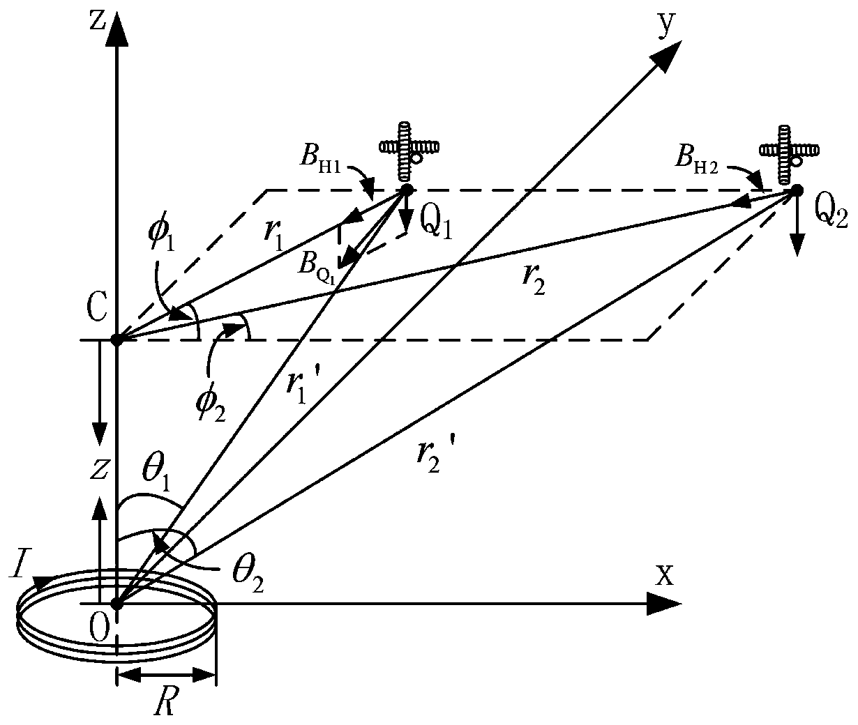
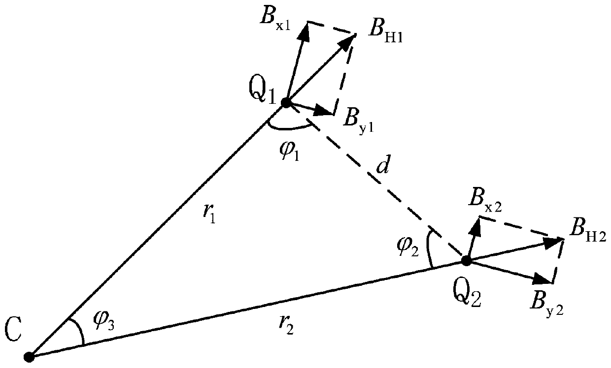
[0067] In Embodiment 2 of the present invention, in order to determine the depth of the transmitter, the receiver Q on the ground in formula (22) 1 Magnetic induction penetrating positioning signal at point Carrying out vector decomposition, we get The horizontal component B of H1 and vertical component B Z1 , transform the spherical coordinate system used in formula (22) into a rectangular coordinate system, and Q 1 The spherical coordinates of the point (r′ 1 ,θ,φ 1 ) is simplified to (r 1 ,z), φ 1 Indicates that the receiver Q 1The angle between the line connecting with the intersection point C and the x-axis, z represents the distance between the transmitter and the ground, deduced with r 1 , the correspondence between z. combined Q 1 , the distance r between two points C 1 , according to Q 1 Magnetic induction penetrating positioning signal strength at a point The distance z between the transmitter and the ground is determined.

[0068] Such as Figure 4


PUM


Abstract

The invention provides a magnetic induction through-the-earth positioning method based on path loss, and belongs to the technical field of magnetic induction through-the-earth positioning. According to the method, the horizontal distance between the transmitter and the receivers is calculated by utilizing the geometrical relationship between the intersection points of the central axes of the two receivers and a transmitter coil on the ground and the ground, the corresponding relation between the magnetic induction through-the-earth positioning signal intensity at a certain point on the groundunder a rectangular coordinate system and the depth from the underground transmitter to the ground is derived, and the distance between the transmitter and the ground is determined according to the magnetic induction through-the-earth positioning signal intensity at the certain point on the ground, so that the vertical depth positioning based on path loss is achieved. According to the method, thechange rules of the horizontal component, the vertical component and the sum vector of the through-the-ground positioning signal along with the distance between the underground transmitter and the ground is analyzed, the one-to-one correspondence relationship between the positioning signal and the vector and the depth between the transmitter and the ground is established, and more accurate through-the-ground positioning of the signal attenuation based on a ground medium is realized.

Description


Claims


Application Information

Patent Timeline
Owner BEIJING JIAOTONG UNIV
Why Eureka
Try Eureka