High-resolution differential confocal imaging system and imaging method based on tangential polarized light

A technology of tangentially polarized light and tangentially polarized light, which is applied in the field of optical microscopy, can solve problems such as artifacts, and achieve the effects of avoiding artifacts and high imaging resolution

Inactive Publication Date: 2020-06-09
JIANGSU INST OF MEDICAL DEVICE TESTING +1
View PDF5 Cites 0 Cited by
  • Summary
  • Abstract
  • Description
  • Claims
  • Application Information

AI Technical Summary

Benefits of technology

This technology uses an optically active material called Liquid Crystals (LC) that can change its molecular orientation when exposed to specific types or directions of electromagnetic radiation. By introducing this special type of LC with different orientations at one end of the device, two images may be captured simultaneously without any distortion caused during exposure time. These techniques have improved accuracy compared to traditional lasers used for creating 3D models due to their ability to capture fine detail accurately over large areas quickly while also reducing errors associated with other processes involved.

Problems solved by technology

This patented technical problem addressed by this patents relates to how to enhance laserscence microscopy (LSCM) images with higher spatial accuracy than current techniques like electron beam lithography or X ray fluorescent analysis.

Method used


Image

  • High-resolution differential confocal imaging system and imaging method based on tangential polarized light
  • High-resolution differential confocal imaging system and imaging method based on tangential polarized light
  • High-resolution differential confocal imaging system and imaging method based on tangential polarized light

Examples


Embodiment 1

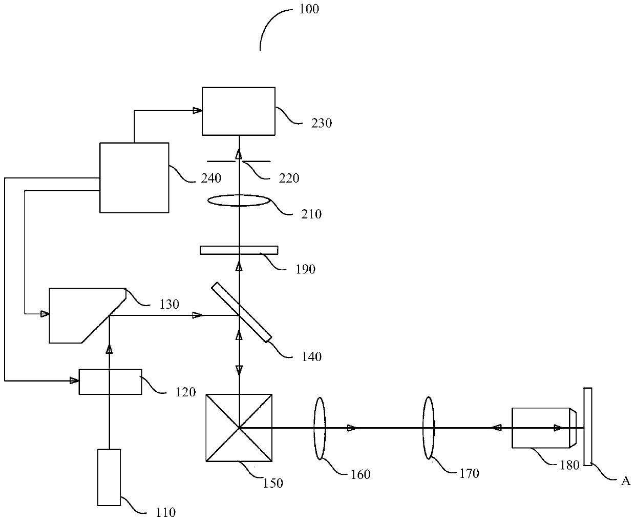
[0026] see figure 1 , a schematic structural diagram of a high-resolution differential confocal imaging system 100 based on tangentially polarized light provided in Embodiment 1 of the present invention, including: a laser 110, a tangential polarization converter 120, a liquid crystal spatial light modulator 130, and a dichromatic mirror 140 , scanning galvanometer 150 , scanning lens 160 , tube lens 170 , objective lens 180 , fluorescence filter 190 , focusing lens 210 , pinhole 220 , photomultiplier tube 230 and control unit 240 .

[0027] Specifically, the tangential polarization converter 120 , the liquid crystal spatial light modulator 130 and the photomultiplier tube 230 are all connected to the control unit 240 .

[0028] The working principle of the high-resolution differential confocal imaging system 100 based on tangentially polarized light provided by the present invention is as follows:

[0029] The laser beam emitted by the laser 110 passes through the tangential po

Embodiment 2

[0046] In this embodiment, the present invention also provides a high-resolution differential confocal imaging method based on tangentially polarized light, comprising the following steps:

[0047] Step S110: the laser beam emitted by the laser 110 passes through the tangential polarization converter 120 to form tangentially polarized light, and the tangentially polarized light forms a uniform phase after passing through the liquid crystal spatial light modulator 130 and then enters the the dichroic mirror 140, and enter the scanning vibrating mirror 150 after being reflected by the dichroic mirror 140, and then focus on the sample after passing through the scanning lens 160, the tube lens 170 and the objective lens 180 in sequence, and Excite the sample to generate a fluorescent beam; the fluorescent beam enters the dichroic mirror 140 after sequentially passing through the objective lens 180, the tube lens 170, the scanning lens 160 and the scanning galvanometer 150, and passes


PUM


Abstract

The invention provides a high-resolution differential confocal imaging system and method based on tangential polarized light. A liquid crystal spatial light modulator and a tangential polarization converter are introduced into a laser spot scanning confocal imaging illumination light path, tangential polarized light is introduced into the illumination light path through the tangential polarizationconverter, firstly, a uniform phase is introduced into the liquid crystal spatial light modulator, primary confocal imaging is carried out, and a first image is obtained; by introducing a 0-2pi spiral phase on the liquid crystal spatial light modulator and performing confocal imaging again, a second image is obtained, a high-resolution differential confocal image based on the tangential polarizedlight can be obtained according to the first image and the second image, and the spot size of the point spread function of the high-resolution differential confocal image based on the tangential polarized light is remarkably smaller than that of a point spread function during conventional laser scanning confocal microscopic imaging, so that the high-resolution differential confocal image has highimaging resolution, and the defects of artifacts and the like caused by an image processing method are avoided.

Description


Claims


Application Information

Patent Timeline
Owner JIANGSU INST OF MEDICAL DEVICE TESTING
Why Eureka
Try Eureka