Decoupled alignment axis for fold mirror adjustment

a technology of alignment axis and fold mirror, which is applied in the direction of optics, optical elements, instruments, etc., can solve the problems of not easy to determine that the correct rotation has been achieved, time-consuming iterative process, and the need for translation and translation of scanlines

Inactive Publication Date: 2005-03-22
CARESTREAM HEALTH INC
View PDF1 Cites 0 Cited by
  • Summary
  • Abstract
  • Description
  • Claims
  • Application Information

AI Technical Summary

Benefits of technology

This patent describes an improved method for adjusting the final folded mirror in a laser scanning optical system. It simplifies the process by allowing for easy changes without requiring multiple steps or complicated calculations.

Problems solved by technology

The technical problem addressed in this patent is how to reduce the size and complexity of a CR reader system without compromising its performance. Specifically, it involves adding a final folded mirror to the optical path between the light source and the phosphor screen. By adjusting the reflective surfaces of the mirror, the system can achieve better resolution and control over the radiation pattern. Additionally, the system includes a sensor located near one end of the mirror to detect if the scan line is advanced towards the right side before turning on the camera. If the scan line is detected, the mirror is then moved forward to compensate for any misalignment caused by the movement of the scanline.

Method used


Image

  • Decoupled alignment axis for fold mirror adjustment
  • Decoupled alignment axis for fold mirror adjustment
  • Decoupled alignment axis for fold mirror adjustment

Examples


Embodiment Construction

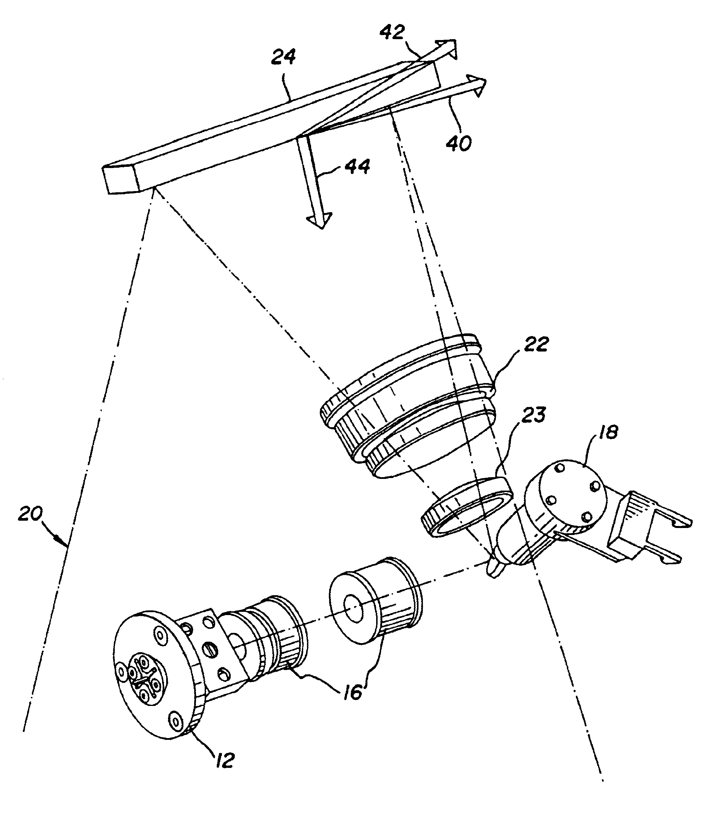
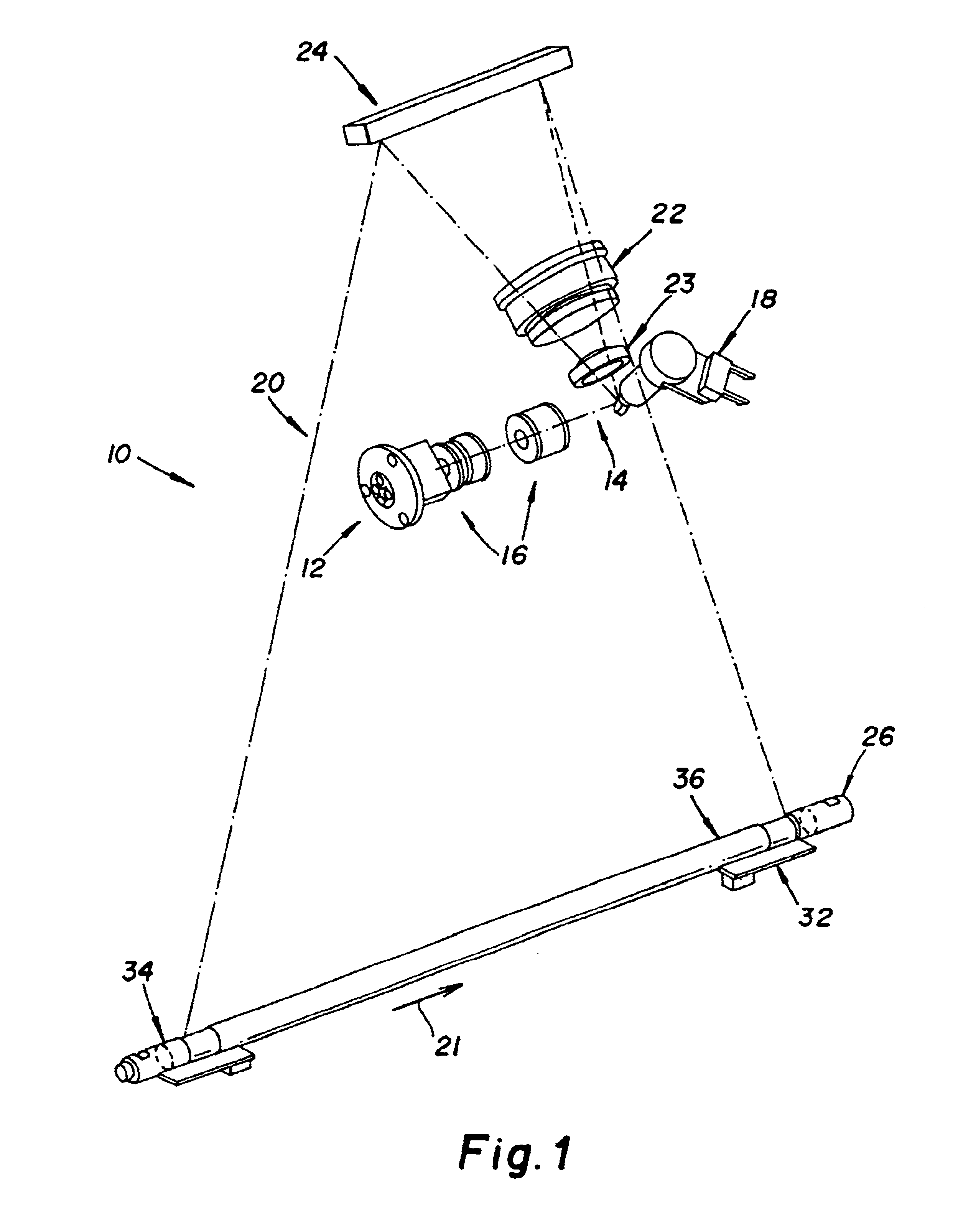
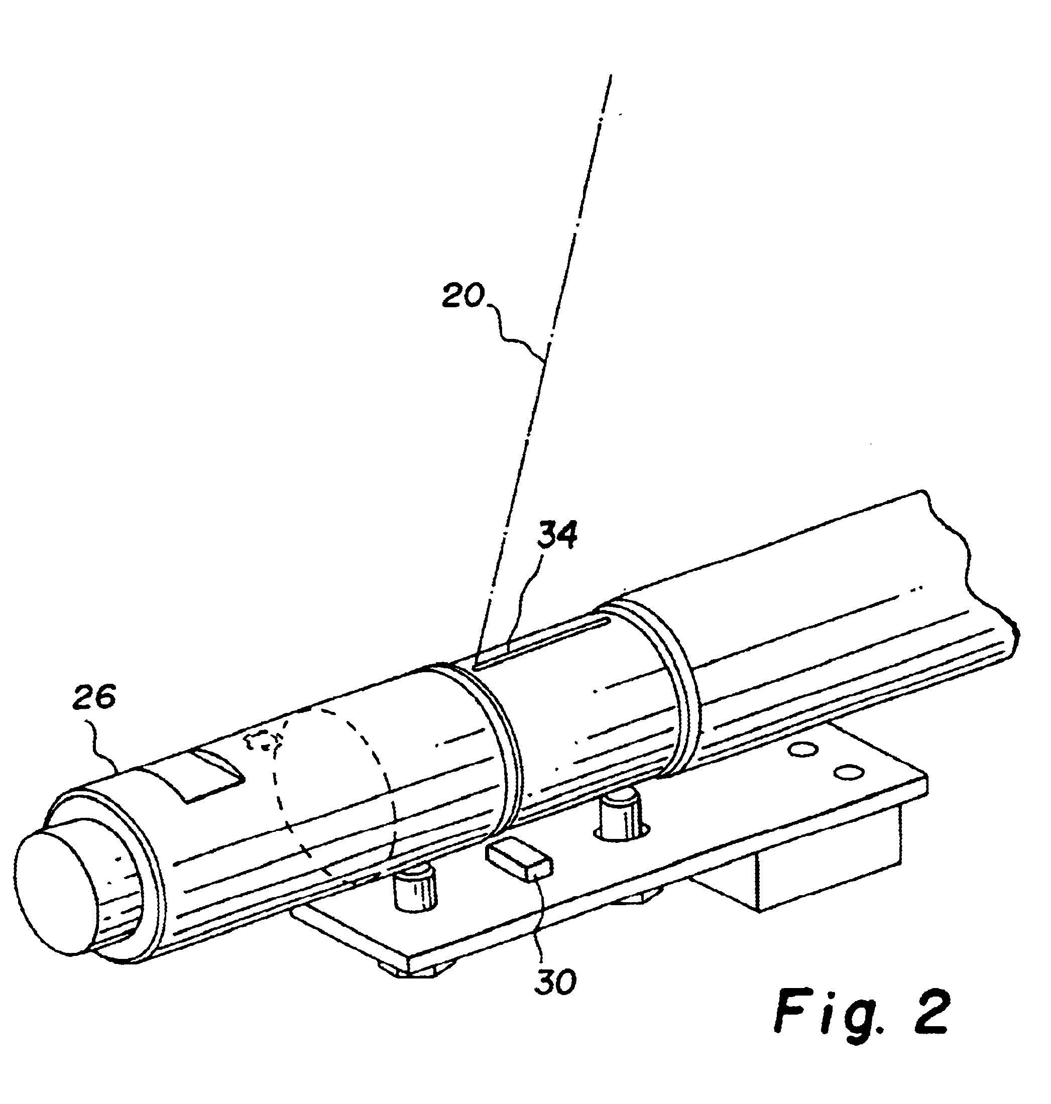
Referring now to FIGS. 1-3, there is shown a laser scanning optical system for use in a computed radiography scanning system (or any other similar scanning system) incorporating an embodiment of the present invention. As shown, laser scanning optical system 10 includes a laser diode 12 which produces a laser beam 14 shaped by shaper lens elements 16. A reciprocating galvonometer mirror 18 produces a laser beam scan line 20 in a fast scan direction 21 shaped by F-theta lens 22 and lens 23. A final fold mirror 24 directs scan line 20 onto platen 26. Platen 26 establishes an imaging region for a storage phosphor plate transported in a slow scan direction 28 over platen 26. Sensors 30 and 32 are located at the ends of scan line 20 and are activated by laser beam 14 passing through respective slits 34 and 36 in platen 26. A rotating multifaceted polygon mirror can also be used in place of the reciprocating galvonometer mirror 18 to produce laser beam scan line 20.

FIG. 3 illustrates the thre


PUM


Abstract

A method of laser beam alignment in a laser scanning system comprising: providing an elongated planar mirror having left and right ends for directing a laser beam scan line to a scan line imaging region spaced from the mirror; detecting left and right spots of the laser beam scan line to determine whether the laser beam is aligned in the imaging region, and if it is not; first rotating the elongated mirror about a first axis extending along the scan line direction of the mirror until the right spot is detected; second rotating the mirror about a second axis located near the right end of the mirror, the second axis extending in the plane of the mirror at angle to the first axis until the left spot is detected.

Description


Claims


Application Information

Patent Timeline
Owner CARESTREAM HEALTH INC
Why Eureka
Try Eureka