Aircraft attitude adjustment path optimization method based on rotation

A path optimization and aircraft technology, applied in the direction of instruments, attitude control, non-electric variable control, etc., can solve problems such as mission failure and lack of flexibility

Active Publication Date: 2020-06-30
BEIHANG UNIV
View PDF8 Cites 0 Cited by
  • Summary
  • Abstract
  • Description
  • Claims
  • Application Information

AI Technical Summary

Benefits of technology

This technology allows an aircraft's flight control system (FCS) automatically sets its orientation with reference to different directions by analyzing factors like altitude or star position. It then uses these optimized settings to achieve specific objectives such as maintain stability during flights.

Problems solved by technology

This patented technology describes how certain types of systems can help improve navigational performance during flights by automatically compensating any deviations from their original position caused by factors like external forces (such as wind) that could affect course direction.

Method used


Image

  • Aircraft attitude adjustment path optimization method based on rotation
  • Aircraft attitude adjustment path optimization method based on rotation
  • Aircraft attitude adjustment path optimization method based on rotation

Examples


Embodiment Construction

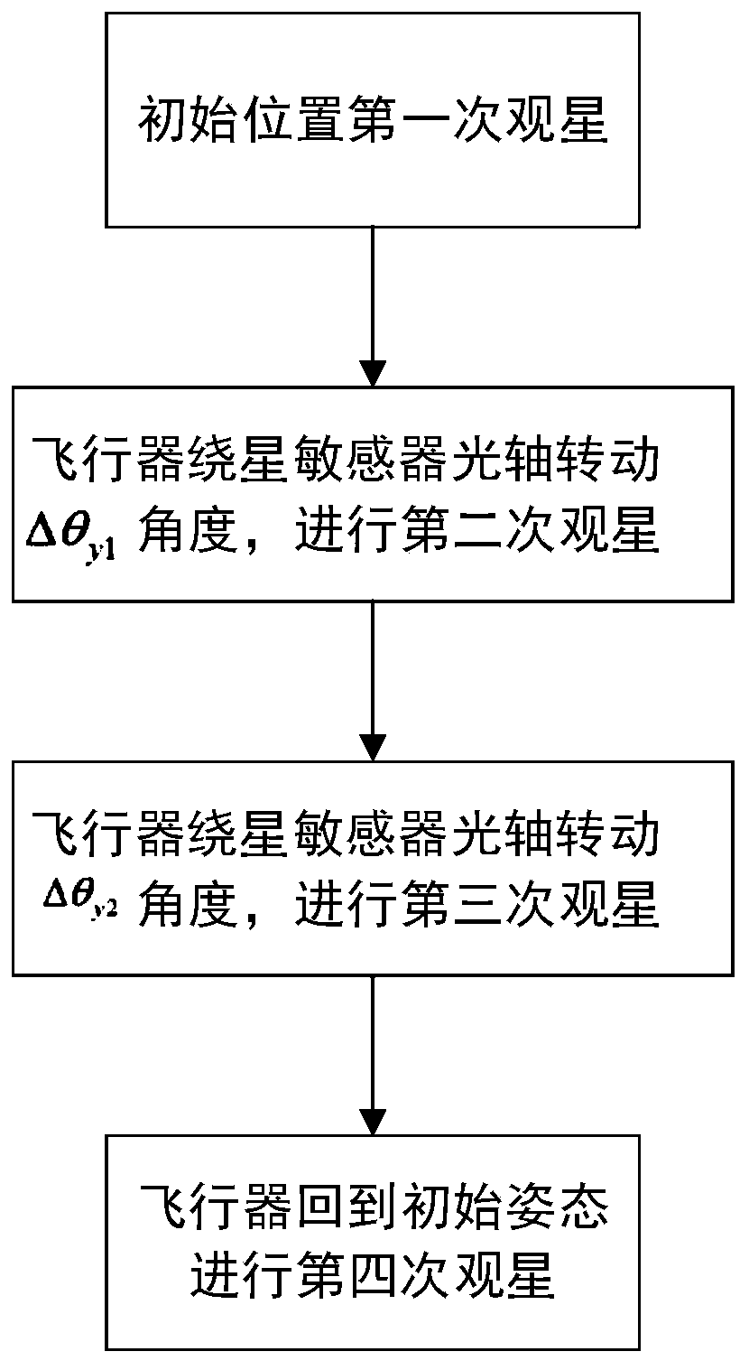
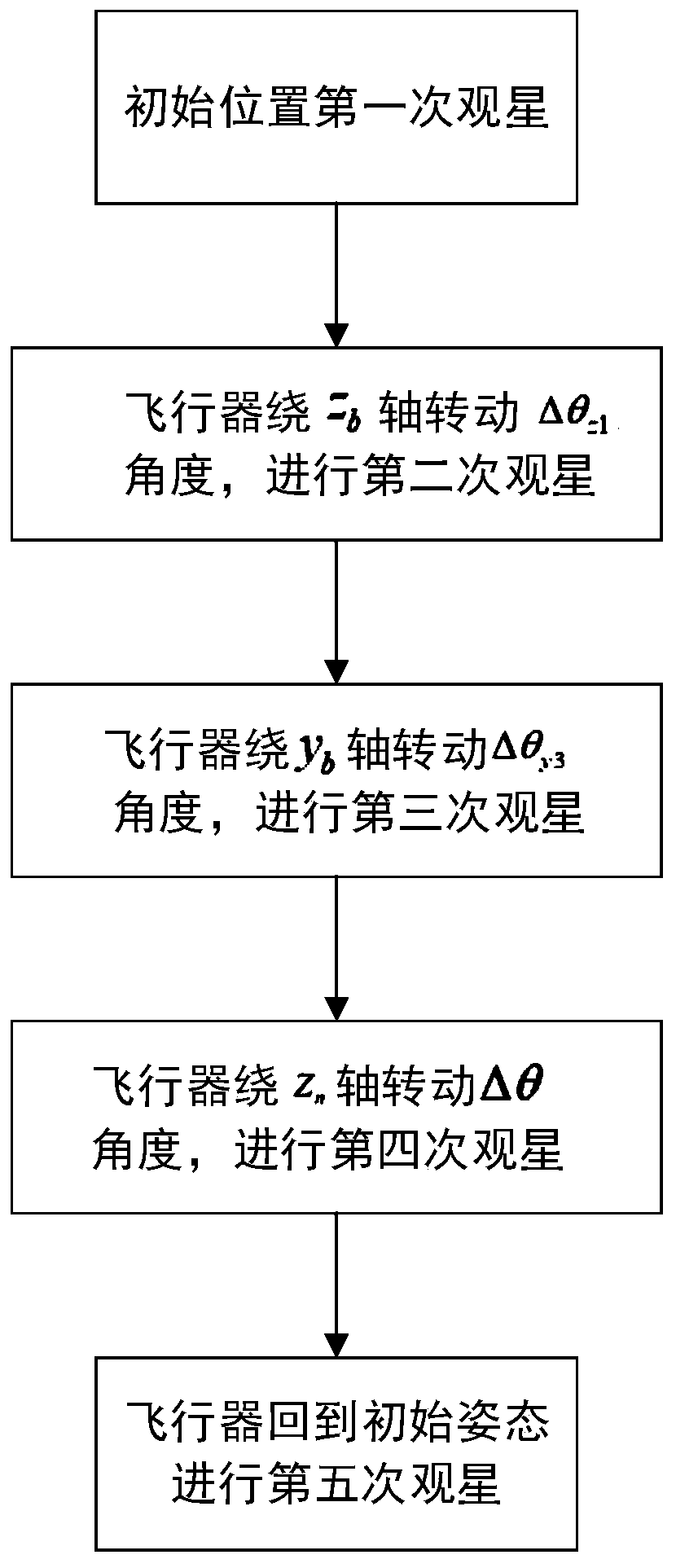
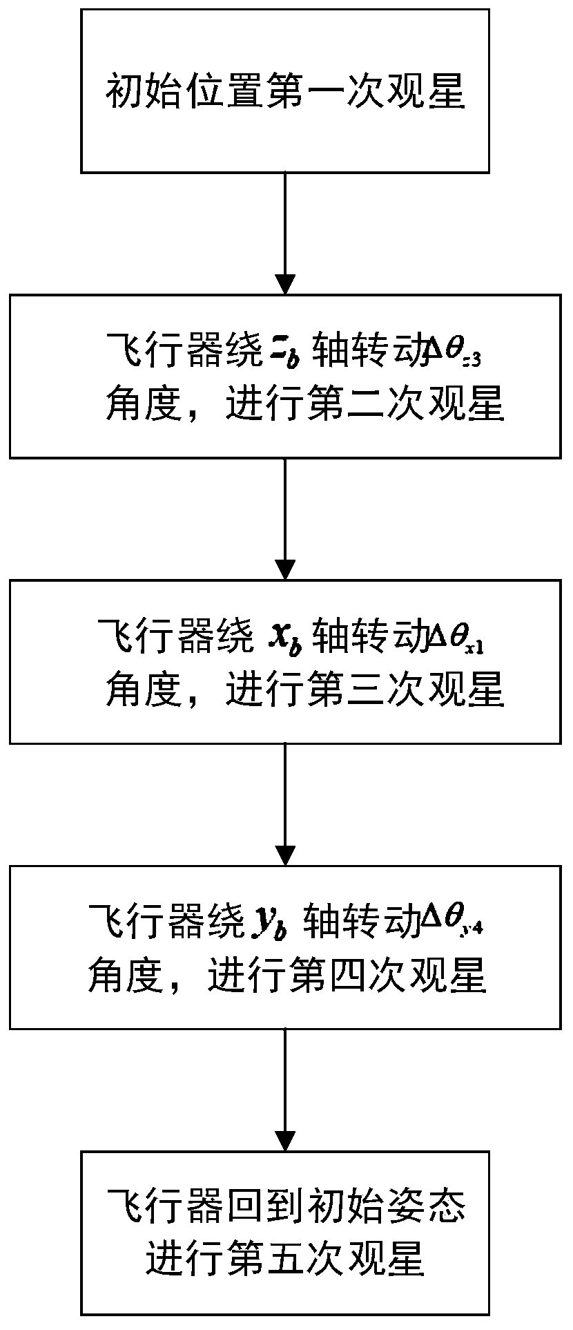
[0114] For the sake of illustration, the relevant coordinate axes are defined first. In the present invention, the star sensor and the optical fiber inertial set are installed in strapdown, and the roll axis of the aircraft carrier is defined as y b axis, the pitch axis of the carrier is x b axis, the carrier heading axis is z b axis, x b 、y b ,z b The three axes conform to a right-handed coordinate system, and the x b 、y b ,z b Denote it as the b system; define the navigation system x n axis points due east, y n Axis points to true north, z n axis pointing towards the sky in the direction of gravity, the x n 、y n ,z n It is recorded as the n system, where the optical axis of the star sensor and the rolling axis of the aircraft carrier y b The axes point the same way. The present invention will be further described below in conjunction with the accompanying drawings, but it should be understood that the protection scope of the present invention is not limited theret


PUM


Abstract

The invention belongs to the technical field of attitude control, and relates to an aircraft attitude adjustment path optimization method based on rotation. The invention provides an inertia/starlightcombined attitude adjustment star observation sequence aerial autonomous setting method. Rotation freedom degree constraints are divided into three types, namely single-freedom-degree posture adjustment, two-freedom-degree posture adjustment and three-freedom-degree posture adjustment, and aiming at the three types of freedom degree constraints, posture adjustment parameters based on the optimalplatform error angle observation matrix D, namely the optimal design criterion of the optimal rotation angle, are given respectively.

Description


Claims


Application Information

Patent Timeline
Owner BEIHANG UNIV
Why Eureka
Try Eureka