Bi-directional powerful aircraft

A powerful technology for aircraft, applied in the field of aircraft, can solve the problems of slow take-off and instability of aircraft, and achieve the effect of rapid acceleration

Inactive Publication Date: 2018-05-15
王美航
View PDF5 Cites 1 Cited by
  • Summary
  • Abstract
  • Description
  • Claims
  • Application Information

AI Technical Summary

Problems solved by technology

[0002] With the advancement of science and technology, aircraft has gradually come into people's sight, and has been widely used in surveying, agriculture, militar

Method used


Image

  • Bi-directional powerful aircraft

Examples


Embodiment Construction

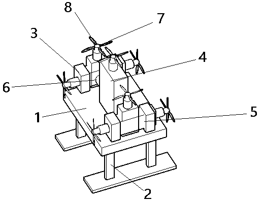
[0010] Now in conjunction with accompanying drawing the present invention is described in detail, a kind of two-way powerful aircraft comprises fuselage 1, frame 2, left motor fixing device 3, middle motor fixing device 4, right motor fixing device 5, axle post 6, rotor 7 and motor8.

[0011] The fuselage 1 is equipped with a control system and airborne equipment. There are seven motors 8 on the fuselage 1 . There are seven rotors 7 on the fuselage. The left motor fixing device 3 is on the fuselage 1 . The middle motor fixing device 4 is on the fuselage. The right motor fixing device 5 is on the fuselage 1 . There are three motors 8 and rotors 7 on the left motor fixing device 3 . A motor 7 and rotor 6 are arranged on the described middle motor fixing device 4 . There are three motors 8 and rotors 7 on the right motor fixing device 5 . The shaft column 6 passes through the left motor fixing device 3 , the middle motor fixing device 4 and the right motor fixing device 5 and


PUM


Abstract

The invention belongs to the technical field of aircrafts, in particular relates to a bi-directional powerful aircraft. The bi-directional powerful aircraft comprises an aircraft body, an aircraft frame, a left motor fixing device, a medium motor fixing device, a right motor fixing device, a shaft column, rotor wings and motors. The inner portion of the aircraft body is matched with a control system and airborne equipment. Seven motors are arranged on the aircraft body. Seven rotor wings are arranged on the aircraft body. The left motor fixing device is fixedly installed on the aircraft body.The medium motor fixing device is fixedly installed on the aircraft body. The right motor fixing device is fixedly installed on the aircraft body. Three motors and three rotor wings are arranged on the left motor fixing device. One motor and one rotor wing are arranged on the medium motor fixing device. Three motors and three rotor wings are arranged on the right motor fixing device. The shaft column penetrates through the left motor fixing device, the medium motor fixing device and the right motor fixing device and is fixed on the aircraft body. The bi-directional powerful aircraft is safe and stable, and can accelerate rapidly.

Description


Claims


Application Information

Patent Timeline
Owner 王美航
Why Eureka
Try Eureka