Air-resistance type sealing structure and working method

A technology of sealing structure and working method, which is applied in the direction of engine sealing, mechanical equipment, engine components, etc., can solve the problems of large leakage between dynamic and static gaps, achieve the effects of enhancing energy dissipation, reducing gap leakage, and improving safety and economy

Pending Publication Date: 2020-07-28
XIAN XIRE ENERGY SAVING TECH +1
View PDF0 Cites 4 Cited by
  • Summary
  • Abstract
  • Description
  • Claims
  • Application Information

AI Technical Summary

Problems solved by technology

[0004] The purpose of the present invention is to overcome the problem of large leakage between the control dynamic and static gaps,

Method used


Image

  • Air-resistance type sealing structure and working method
  • Air-resistance type sealing structure and working method
  • Air-resistance type sealing structure and working method

Examples


Embodiment Construction

[0024] The present invention will be further described below in conjunction with the accompanying drawings.

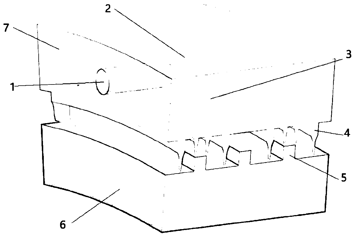
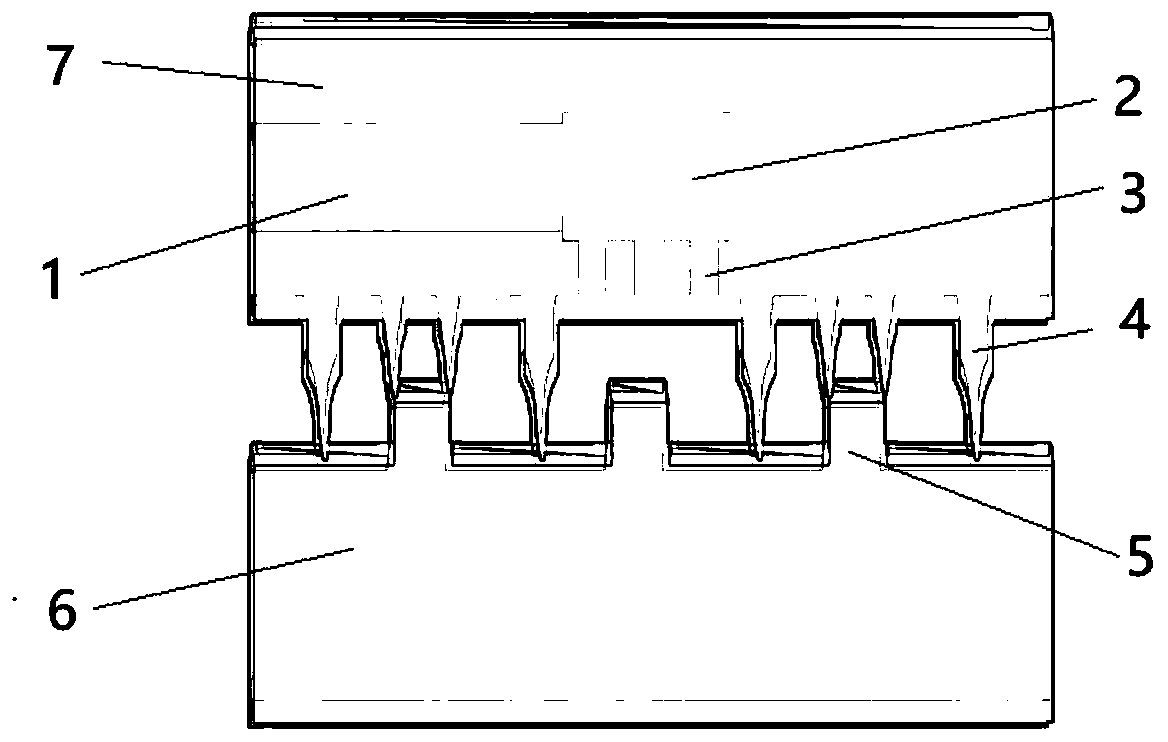
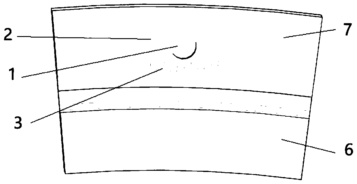
[0025] see Figure 1 to Figure 4 , an air resistance type sealing structure, including a rotor 6 and a stator block 7, the stator block 7 is set outside the rotor 6, the rotor 6 is provided with a boss 5, and the stator block 7 is provided with a seal matching the boss 5 Teeth 4, sealing teeth 4 cooperate with the boss 5 to form a labyrinth seal, the stator block 7 is built with a pressure equalization slow flow chamber 2, and the pressure equalization slow flow chamber 2 communicates with the outside world through the high pressure drainage tube 1, and the high pressure drainage tube 1 flows from the The end face of the stator block 7 communicates with the outside world. The pressure-equalizing slow flow chamber 2 is connected with a number of inner chamber pressure air guide tubes 3 , and all the inner cavity pressure air guide tubes 3 face the boss 5 on the stator bloc


PUM

PropertyMeasurementUnit
Apertureaaaaaaaaaa
Apertureaaaaaaaaaa

Abstract

The invention discloses an air-resistance type sealing structure and a working method. The air-resistance type sealing structure is structured such that a high pressure drainage pipe is additionally arranged on the wall surface of an upstream end of an air flow of a conventional labyrinth seal stationary sub block, part of high pressure air flow is introduced into a pressure equalizing slow flow chamber in the stationary sub block through the drainage pipe, and the air flow is pressed in uniformly further through a pressure inflating air guide pipe in an inner cavity. By means of an air flow pressure inflating method, the effective pressure difference in a front seal area is reduced, so that the original power leaked from a gap is reduced from the origin. Meanwhile, under induction of highpressure jet entrainment, a large-dimension vortex structure which fills the whole chamber is further formed in a middle cavity of the seal gap connected to the pressure inflating air guide pipe in the inner cavity, so that the energy dissipation is enhanced, the leakage amount of the gap is reduced and the safety and economic benefit of operation of a unit are improved.

Description


Claims


Application Information

Patent Timeline
Owner XIAN XIRE ENERGY SAVING TECH
Why Eureka
Try Eureka