Automatic adsorption mechanism driving system for protecting eardrums

A technology of adsorption mechanism and drive system, applied in signal transmission system, earpiece/headphone accessories, non-electrical signal transmission system, etc., can solve the problems of eardrum damage, inability to know accurately, and inability to successfully apply automatic control technology, so as to avoid injury , improve reliability and safety, compact design effect

Inactive Publication Date: 2020-07-31
刘春艳
View PDF5 Cites 2 Cited by
  • Summary
  • Abstract
  • Description
  • Claims
  • Application Information

AI Technical Summary

Benefits of technology

This patented technology allows an automatically controlled device called EarPlugs (Headsets) with sensors that detect if they fit into their rings or gums during use without causing harm from being pulled out by external forces like breathing or chewing. It also includes multiple types of infusion devices placed around it's outer surface to help deliver medicine more efficiently through this structure. Overall, these technical features improve the performance and durability of the Headphone Adhesive Mechanism.

Problems solved by technology

This patented technical problem addressed in this patents relates to improving automated controls for earphones with an earpiece attached thereto during sound recording playback operations due to incorrect timing issues caused by the lack of accurate knowledge about how well the earbud can absorb sounds properly.

Method used


Image

  • Automatic adsorption mechanism driving system for protecting eardrums
  • Automatic adsorption mechanism driving system for protecting eardrums
  • Automatic adsorption mechanism driving system for protecting eardrums

Examples


no. 1 example

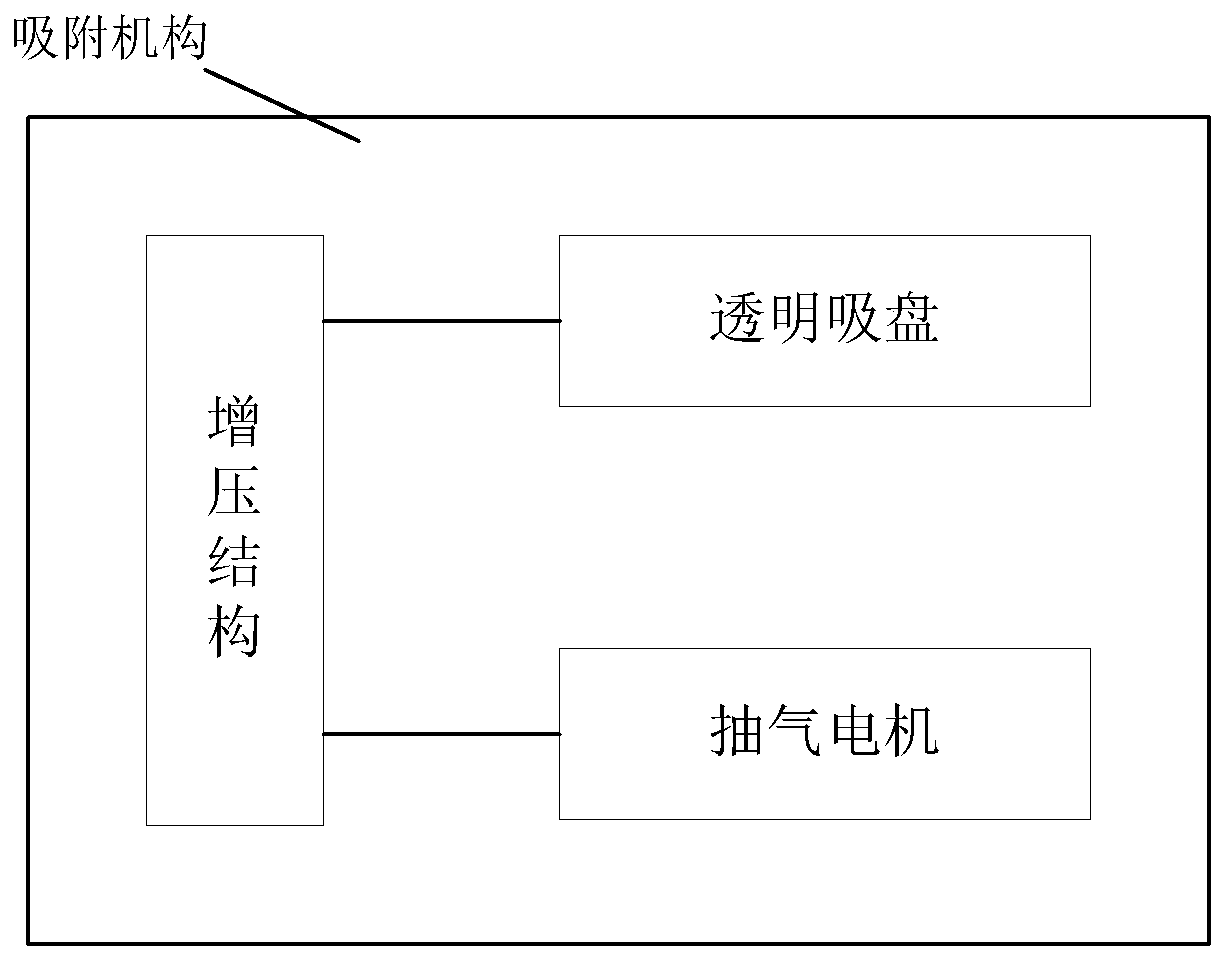
[0031] figure 2 It is a structural block diagram of an automatic adsorption mechanism drive system for eardrum protection shown according to the first embodiment of the present invention, the system includes:

[0032] The adsorption mechanism is arranged at the earplug part of the earphone and deviates from the position of the sound outlet of the earplug part to avoid the central position of the ear hole. When the second driving signal is activated, the adsorption action on the ear body is turned off;

[0033] The adsorption mechanism is composed of a transparent suction cup, a booster structure and an air suction motor, and the transparent suction cup is used to get close to the ear body that deviates from the center of the ear hole when the adsorption mechanism is not performing an adsorption action on the ear body;

[0034] The pressurization structure is arranged at a position where the transparent suction cup is far away from the ear body, and is used for performing a pres

no. 2 example

[0053] image 3 It is a flow chart of the steps of the driving method of the automatic adsorption mechanism for eardrum protection shown according to the second embodiment of the present invention, and the method includes:

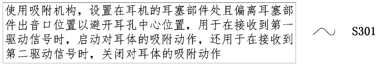
[0054] Step S301: Use the adsorption mechanism, which is set at the earplug part of the earphone and deviates from the sound outlet of the earplug part to avoid the center of the ear hole, and is used to start the adsorption action on the ear body when the first driving signal is received. When receiving the second driving signal, close the adsorption action on the ear body;

[0055] The adsorption mechanism is composed of a transparent suction cup, a booster structure and an air suction motor, and the transparent suction cup is used to get close to the ear body that deviates from the center of the ear hole when the adsorption mechanism is not performing an adsorption action on the ear body;

[0056] The pressurization structure is arranged at a position whe


PUM


Abstract

The invention relates to an automatic adsorption mechanism driving system for protecting eardrums. The system comprises an adsorption mechanism which is arranged at an earplug part of an earphone, deviates from a sound outlet of the earplug part so as to avoid the central position of an earhole, and is used for starting the adsorption action on an ear body when a first driving signal is received,and stopping the adsorption action on the ear body when a second driving signal is received. The adsorption mechanism is composed of a transparent sucking disc, a pressurizing structure and an air exhaust motor; the transparent sucking disc is used for being close to the ear body deviating from the center of the earhole when the adsorption mechanism does not adsorb the ear body; and the pressurizing structure is used for executing a pressurizing action on the transparent sucking disc when receiving the first driving signal. The automatic adsorption mechanism driving system for protecting the eardrums is compact in design and reliable in operation. Since damage to the ear can be avoided while effective adsorption of the ear body is achieved, the reliability and safety of adsorption controlare improved.

Description


Claims


Application Information

Patent Timeline
Owner 刘春艳
Why Eureka
Try Eureka