Electric tool
A technology of electric tools and electric motors, which is applied in the direction of manufacturing tools, portable mobile devices, metal processing equipment, etc., can solve the problems of hindering the improvement of productivity, time-consuming and laborious assembly operations, and rising costs, so as to reduce manufacturing costs, simplify operations, The effect of improving productivity
- Summary
- Abstract
- Description
- Claims
- Application Information
AI Technical Summary
Problems solved by technology
Method used
Image

Examples
Embodiment Construction
[0016] Embodiments of the present invention will be described below based on the drawings.
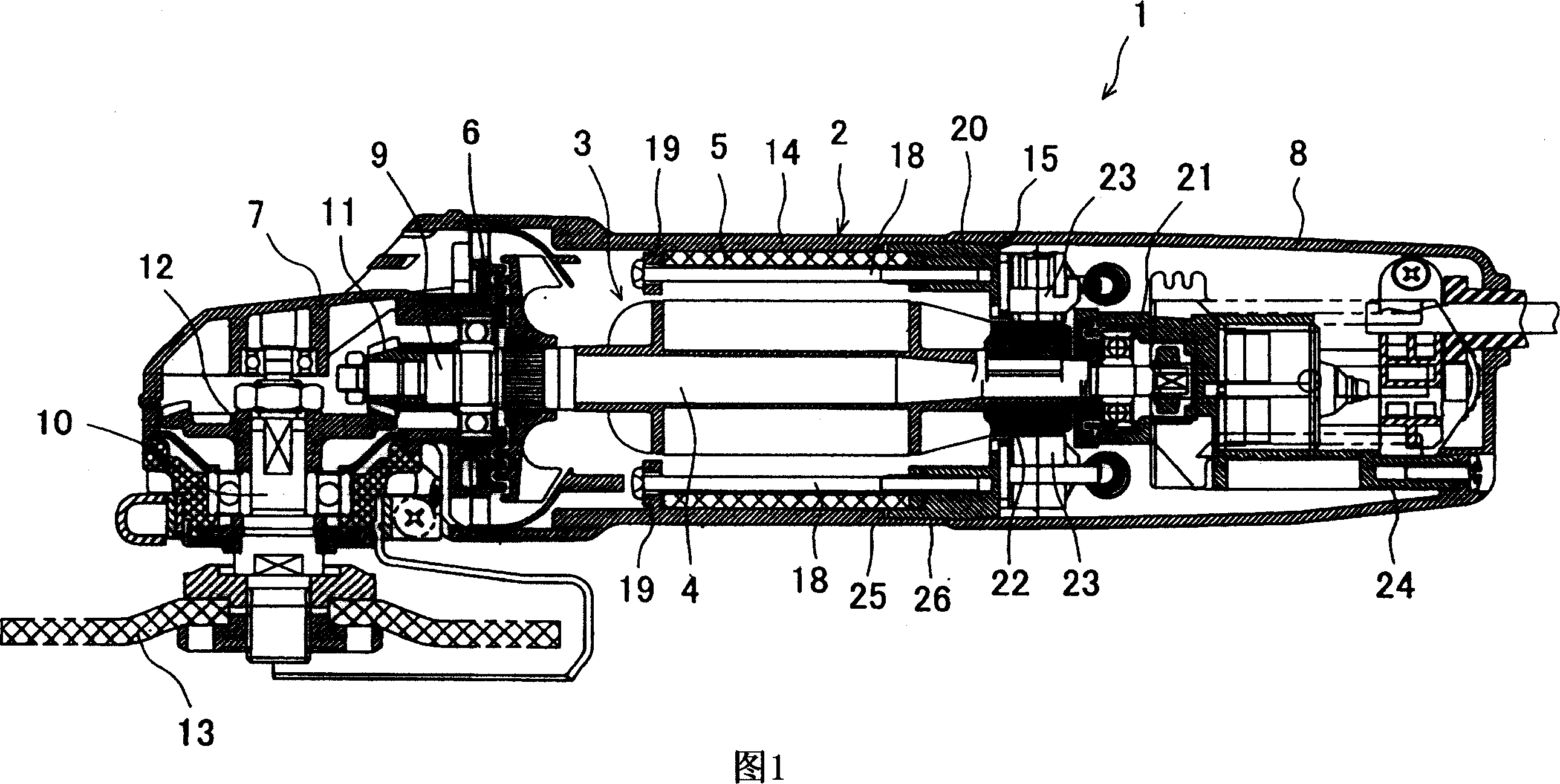
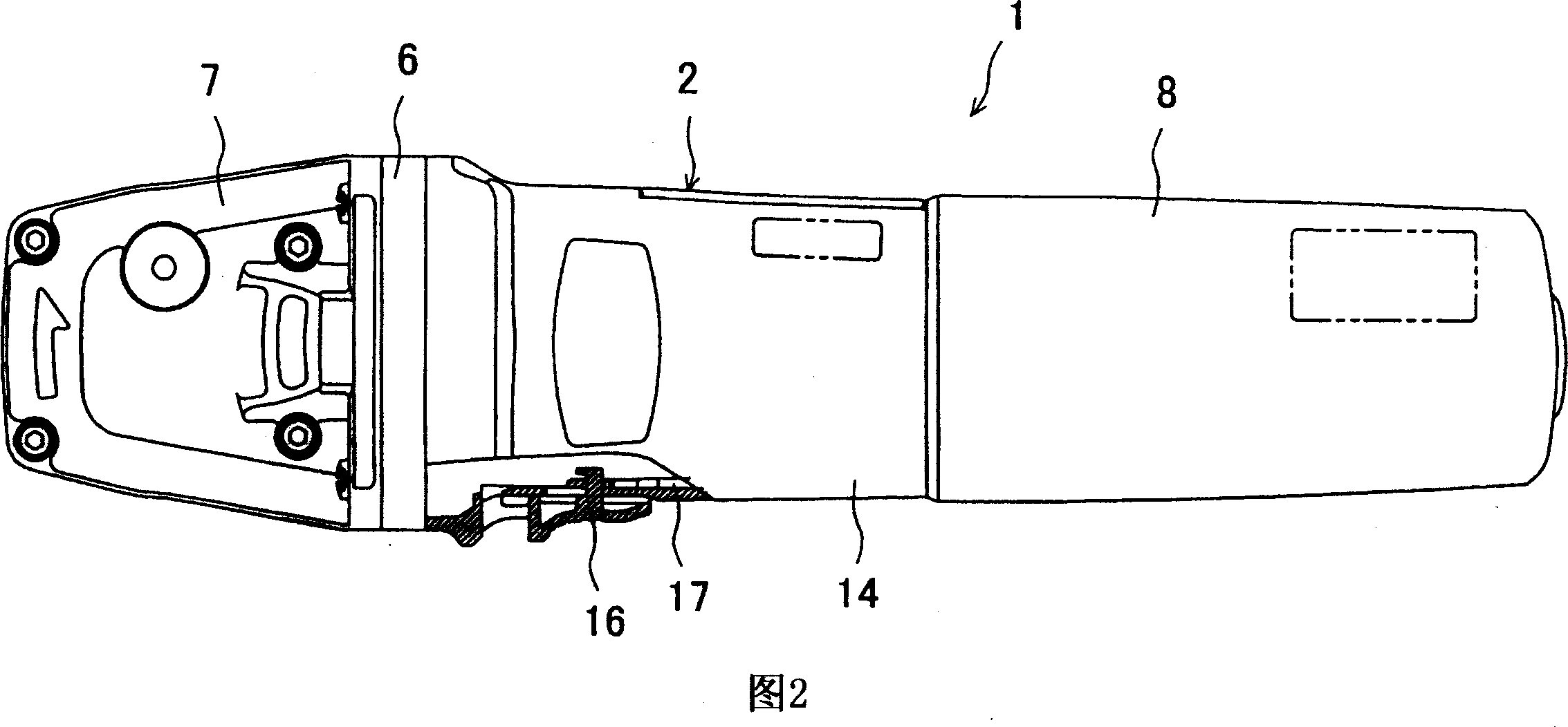
[0017] Fig. 1 is a longitudinal sectional view of an example of an electric tool, that is, a grinder, and Fig. 2 is a plan view, and the grinder 1 is configured as follows: in front of the motor housing 2 (left side of Fig. A gear case 7 is assembled to a bearing plate 6 that pivotally supports the rotor 4 of the gear motor 3, and a rear cover 8 is assembled behind it. Here, the motor casing 2 and the rear cover 8 are made of synthetic resin, and the gear case 7 is made of metal.
[0018] In the gear box 7, the output shaft 9 of the rotor 4 protruding into the gear box 7 is perpendicularly supported to the main shaft 10, and the first bevel gear 11 fixed to the front end of the output shaft 9 is integrally fixed to the main shaft 10 through the first bevel gear 11. The meshing of the second bevel gear 12 can transmit the rotation of the output shaft 9 to the main shaft 10 . A disc-shape
PUM
 Abstract
Description
Claims
Application Information
 - R&D Engineer
- R&D Manager
- IP Professional
- Industry Leading Data Capabilities
- Powerful AI technology
- Patent DNA Extraction
Browse by: Latest US Patents, China's latest patents, Technical Efficacy Thesaurus, Application Domain, Technology Topic.
© 2024 PatSnap. All rights reserved.Legal|Privacy policy|Modern Slavery Act Transparency Statement|Sitemap