Battery pack temperature detection method and device and electric tool

A technology of a temperature detection device and an electric tool, applied in the detection field, can solve the problems of short battery pack discharge time, poor battery life of a single battery pack, false alarm of battery pack over-temperature fault, etc., so as to avoid false alarm of battery pack over-temperature fault. Effect

Inactive Publication Date: 2019-12-10
POSITEC POWER TOOLS (SUZHOU) CO LTD
View PDF6 Cites 0 Cited by
  • Summary
  • Abstract
  • Description
  • Claims
  • Application Information

AI Technical Summary

Benefits of technology

This technology helps detect if there are any problems or issues related to excessive temperatures inside batteries used for electric tools such as drills. By measuring this condition accurately at different points within the battery's structure, preventative measures may be taken beforehand during operation. Additionally, when an issue arises where the battery becomes too hot due to increased resistance from heat transferring into its environment, these technical means help improve cool down times while ensuring optimal performance of the entire system.

Problems solved by technology

This patented describes how batteries can become too hot during use due to their own design that makes them heavier but less safe for users who don't require this type of protection. However, if there were no way to prevent these issues from happening at all, they could cause damage or even worse consequences on other parts inside the device being charged through an external charger.

Method used


Image

  • Battery pack temperature detection method and device and electric tool
  • Battery pack temperature detection method and device and electric tool
  • Battery pack temperature detection method and device and electric tool

Examples


Embodiment Construction

[0047] In order to make the purpose, technical solution and advantages of the present application clearer, the present application will be further described in detail below in conjunction with the accompanying drawings and embodiments. It should be understood that the specific embodiments described here are only used to explain the present application, and are not intended to limit the present application.

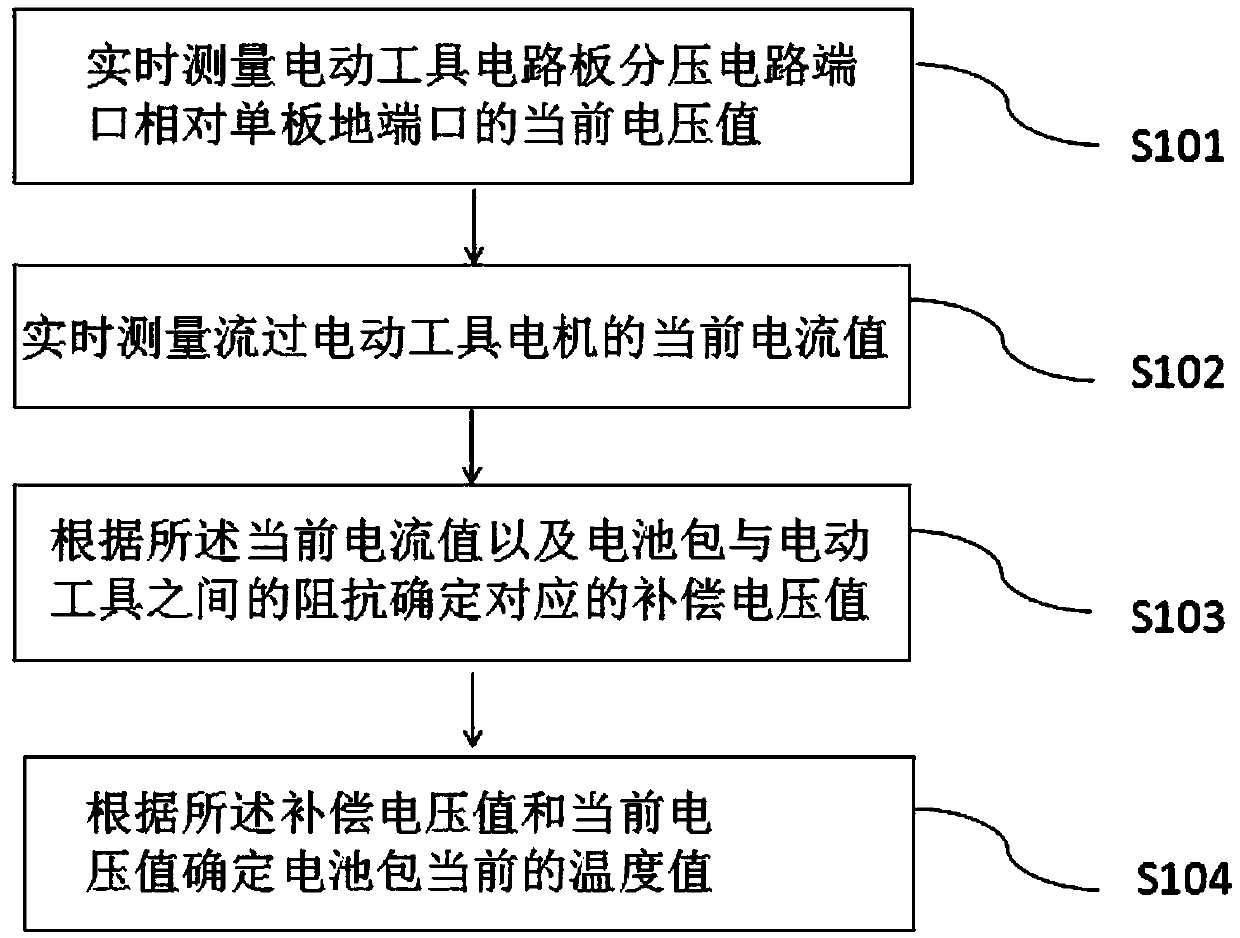
[0048] The embodiment of the present application provides a battery pack temperature detection method, such as figure 1 As shown, the method may include the following steps:

[0049] Step S101: Measure the current voltage value of the port of the voltage divider circuit on the circuit board of the electric tool relative to the ground port of the single board in real time.

[0050] Among them, the electric tool circuit board is a multi-functional circuit board, mainly including the main control board, AD acquisition unit module, AD front-end conditioning module, DA unit modul


PUM


Abstract

The invention relates to a battery pack temperature detection method and device and an electric tool. The method comprises the following steps: measuring the present voltage value of the circuit boardvoltage dividing circuit port of the electric tool relative to a single board ground port in real time; measuring the present current value flowing through the motor of the electric tool in real time; determining the corresponding compensation voltage value according to the present current value and the impedance between the battery pack and the electric tool; determining the present temperaturevalue of the battery pack according to the compensation voltage value and the present voltage value; and stopping the electric tool when the present temperature value of the battery pack meets the preset threshold. The detection device comprises a measurement module used for measuring the real-time current value and voltage value, a compensation module and a temperature determination module. The electric tool comprises a temperature detection device and a control module. The battery core temperature detected by the battery pack temperature detection device can be consistent with the actual temperature, and the accuracy can meet the error requirement.

Description


Claims


Application Information

Patent Timeline
Owner POSITEC POWER TOOLS (SUZHOU) CO LTD
Why Eureka
Try Eureka