Flip-Flop and Frequency Dividing Circuit with Flip-Flop

Active Publication Date: 2011-10-20
MEDIATEK INC
View PDF2 Cites 6 Cited by
  • Summary
  • Abstract
  • Description
  • Claims
  • Application Information

AI Technical Summary

Benefits of technology

[0006]According to a first embodiment of the present disclosure, a flip-flop comprising an input stage and a latch stage is provided. The input stage is capable of converting an input signal to an output signal under the control of a first clock signal and a seco

Problems solved by technology

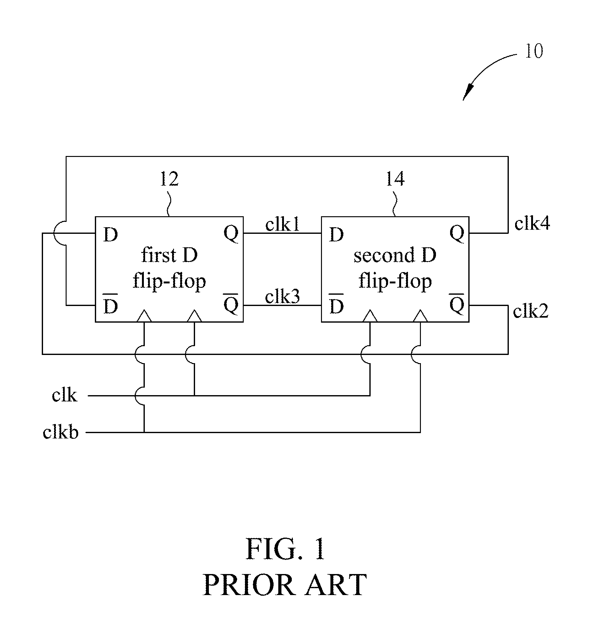
In other words, load conditions of four output ends of the first-stage frequency divider are not completely identical, so that errors occur in the phases of the four output clocks generated by the first-stage frequency divider.
Accordingly, when an operating circuit, e

Method used


Image

  • Flip-Flop and Frequency Dividing Circuit with Flip-Flop
  • Flip-Flop and Frequency Dividing Circuit with Flip-Flop
  • Flip-Flop and Frequency Dividing Circuit with Flip-Flop

Examples


Embodiment Construction

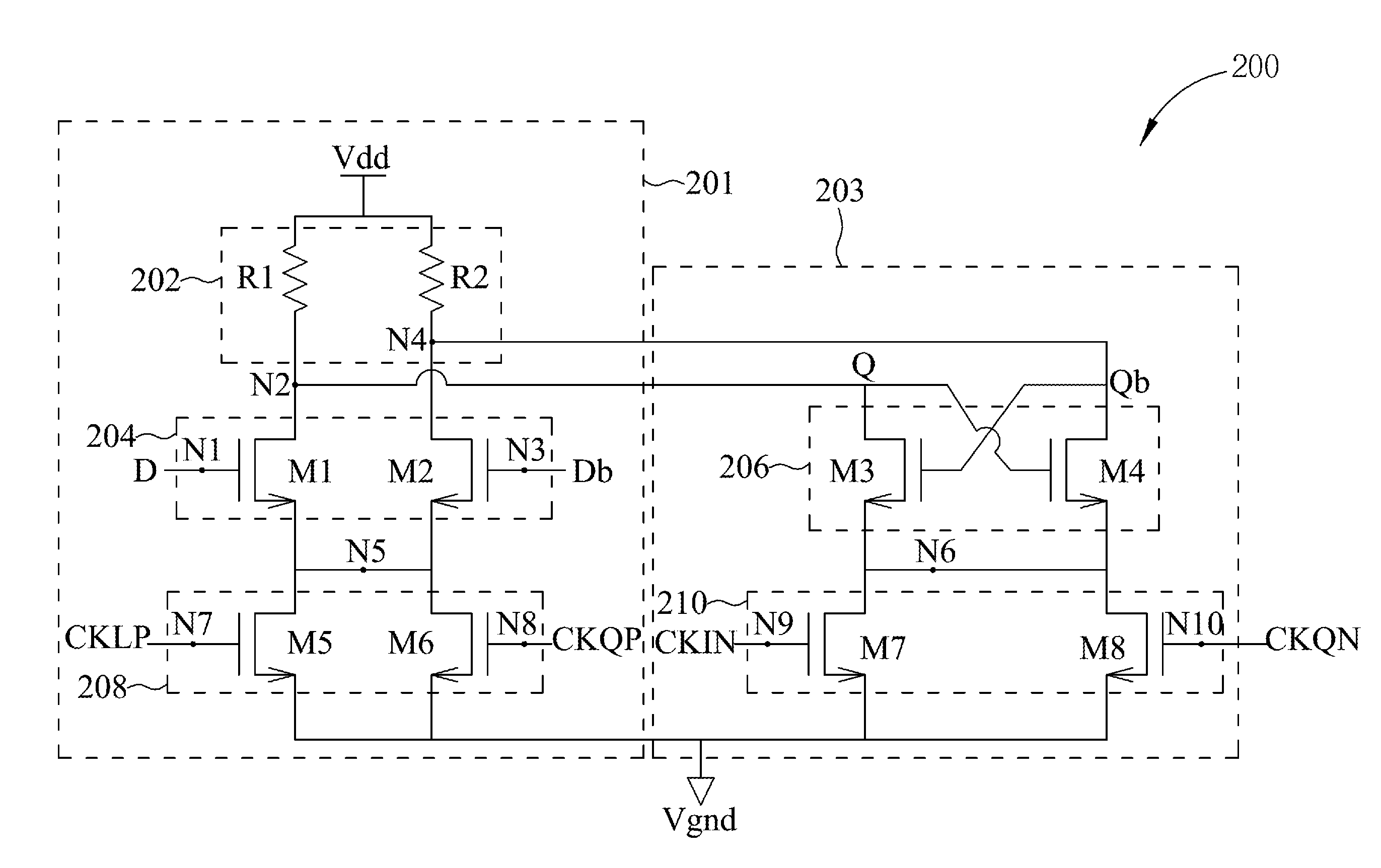
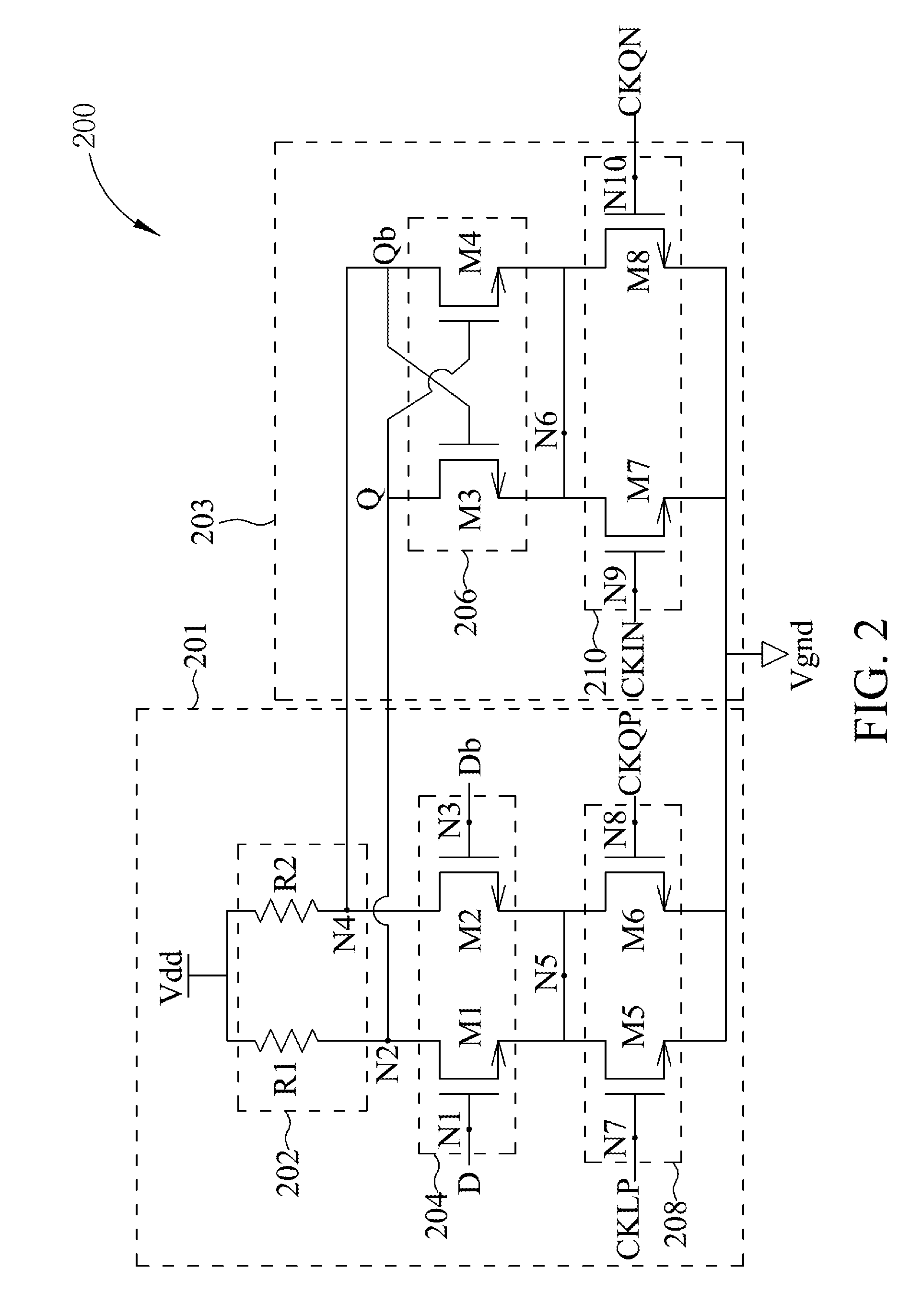
[0012]FIG. 2 is a schematic diagram of a flip-flop 200 in accordance with an embodiment of the present disclosure. The flip-flop 200 comprises an input stage 201 and a latch stage 203. The input stage 201 comprises a load 202, a signal input circuit 204 and a first control circuit 208. The latch stage 203 comprises a cross-coupled pair circuit 206 and a second control circuit 210. The load 202 is coupled to a first voltage level Vdd that is a power supply voltage. The signal input circuit 204 serially connected to the load 202 receives input signal D and Db. In this embodiment, the input signal is a differential pair. The cross-coupled pair circuit 206 coupled to a connection node of the load 202 and the signal input circuit 204 generates a differential pair of output signals Q and Qb. The first control circuit 208 coupled between the signal input circuit 204 and a second voltage level Vgnd receives a first clock signal CKIP and a second clock signal CKQP, and the second voltage level


PUM


Abstract

Various embodiments of a flip-flop and a frequency dividing circuit are provided. In one aspect, a flip-flop includes an input stage and a latch stage. The input stage is capable of converting an input signal to an output signal under the control of a first clock signal and a second clock signal. The latch stage is capable of latching the output signal under the control of a third clock signal and a fourth clock signal. The first clock signal, the second clock signal, the third clock signal and the fourth clock signal have different phases.

Description


Claims


Application Information

Patent Timeline
Owner MEDIATEK INC
Why Eureka
Try Eureka