Deep bed underflow process for enhanced nitrogen removal advanced treatment of low-pollution sewage

A technology with advanced treatment and low pollution, which is applied in the field of deep bed undercurrent to ensure stable operation.

Inactive Publication Date: 2020-08-11
山东省环科院环境工程有限公司
View PDF6 Cites 1 Cited by
  • Summary
  • Abstract
  • Description
  • Claims
  • Application Information

AI Technical Summary

Problems solved by technology

[0022] Aiming at the deficiencies of existing subsurface flow constructed wetlands, the present invention proposes a deep bed subsu

Method used


Image

  • Deep bed underflow process for enhanced nitrogen removal advanced treatment of low-pollution sewage

Examples


specific Embodiment

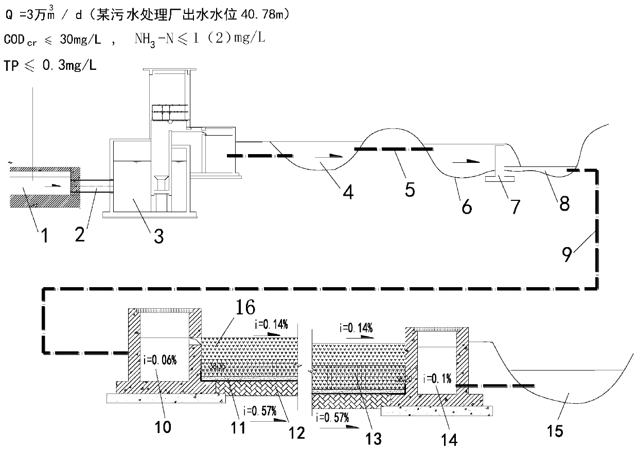
[0050] The flow rate of the treated sewage treatment plant tail water is 20000m 3 / d, wherein the average water depth of the aerobic stabilization pond 4 is 0.8m, and the hydraulic retention time is 0.6d.

[0051] The aeration drop weir 7 between the first-level surface flow wetland and the second-level surface flow wetland is separated. The design drop height of the aeration drop weir 7 is 60cm, and the design drop depth is 20cm. The total area of ​​the surface flow wetland is 12000m 2 . The ratio of the length of the primary surface flow wetland to the length of the secondary surface flow wetland is 1:2. The aspect ratio of each level of surface flow wetland is 3:1.

[0052] The design average water depth of the first-level surface flow wetland is 0.6m, and the nitrifying bacteria agent is added to the first-level surface flow wetland. The lower is 0.4kg / m 3 .

[0053] The average design water depth of the secondary surface flow wetland is 0.8m, and the surface hydrau


PUM


Abstract

The invention relates to a deep bed underflow process for enhanced nitrogen removal advanced treatment of low-pollution sewage. According to the process, sewage is enabled to flow through a surface flow constructed wetland and a deep bed horizontal subsurface flow wetland in sequence; the surface flow constructed wetland comprises a first-stage surface flow wetland and a second-stage surface flowwetland; a nitrifying bacteria inoculant is added into the first-stage surface flow wetland; an aeration drop weir is arranged at the tail end of the first-stage surface flow wetland; wherein the deep-bed horizontal subsurface flow wetland is sequentially paved with a breathable impermeable sand layer, a filter layer, a denitrifying bacterium agent composite carbon source layer and an ecological gravel filler layer from bottom to top; tail water of the surface flow constructed wetland enters the deep bed horizontal subsurface flow wetland through a water collecting weir and a water passing culvert pipe and then is discharged through a water distribution channel, a subsurface flow wetland main body and a water collecting channel of the deep bed horizontal subsurface flow wetland. Accordingto the invention, the problems of nitrification reaction aeration of the subsurface wetland, lack of a carbon source in denitrification and low hydraulic load and large occupied area of the subsurfacewetland are solved, the stable operation of artificial constructed wetland system is ensured, and the low-pollution sewage is subjected to deep enhanced denitrification treatment.

Description


Claims


Application Information

Patent Timeline
Owner 山东省环科院环境工程有限公司
Why Eureka
Try Eureka