Filtering protection structure for ophthalmic laser operation

A protective structure and ophthalmic laser technology, applied in the field of medical surgical instruments, can solve the problems of poor adjustment effect of filter flexibility, poor surgical sight of operators, and inability to replace the filter, so as to meet the needs of protective use and ensure stability , the effect of lengthening

Inactive Publication Date: 2020-08-14
杨国丽
View PDF1 Cites 1 Cited by
  • Summary
  • Abstract
  • Description
  • Claims
  • Application Information

AI Technical Summary

Benefits of technology

This patented technology helps prevent damage from surgeries while still allowing operators to see through an eyepiece lens attached to their headset's optical equipment. It includes various technical features such as improved safety measures or enhanced visualization capabilities when inserting filters within the device housing. Additionally, it allows users to easily change settings without having to disassemble components themselves. Overall, this innovation improves overall performance and efficiency in medical procedures.

Problems solved by technology

This patented technical problem addressed in this patents relates to improving the flexibleness or adjustability of filters during ophthaumics procedures such as Laser LASIK (laser microsurgery) surgery due to their long use over time. Current methods involve manually replacing worn parts frequently without ensuring proper sterility after cleaning them afterwards. Additionally, current solutions have limited options for customizing the filter design based upon specific needs.

Method used


Image

  • Filtering protection structure for ophthalmic laser operation
  • Filtering protection structure for ophthalmic laser operation
  • Filtering protection structure for ophthalmic laser operation

Examples


Embodiment

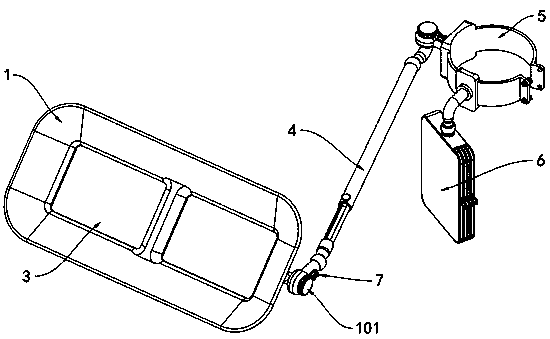
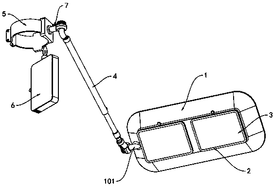
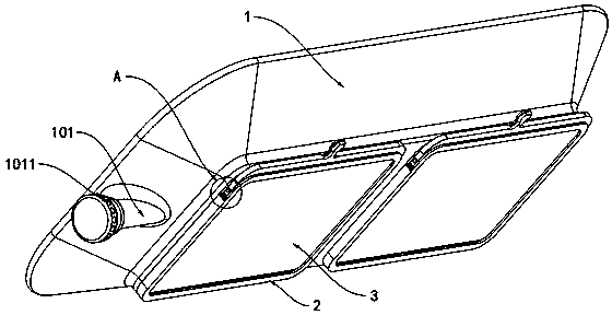
[0036] as attached figure 1 to attach Figure 12 Shown:

[0037]The invention provides a filter protection structure for ophthalmic laser surgery, comprising a light-shielding protective plate frame 1, an assembly frame 2, a light filter plate 3, an adjustment connecting rod 4, a storage box 6 and a limit mechanism 7; the light-shielding protective plate There is a connecting shaft 101 at the right end of the frame 1, and sixteen limiting shaft grooves 1011 are provided on the outside of the connecting shaft 101 in a circular shape; the assembly frame 2 is a square frame structure, and there are two in total, and the two assembly frames 2 are left and right Symmetrically installed on the outside of the light-shielding protective plate frame 1; the light filter plate 3 is a square sheet structure, and the light filter plate 3 is located inside the assembly frame 2; 5 are connected, and the outside of the rear connector 403 provided with the rear end of the adjusting link 4 is su


PUM


Abstract

The invention provides a filtering protection structure for ophthalmic laser surgery, and relates to the technical field of medical surgical instruments. The structure comprises assembly frames, filter plates and an adjusting connecting rod; a connecting shaft is arranged at the right end of a light blocking protection plate frame, and sixteen limiting shaft grooves are formed in the outer portionof the connecting shaft in a surrounding mode; the two assembling frames are of a square frame-shaped structure and are installed outside the light blocking protection plate frame in a bilateral symmetry mode; and the filter plates are of a square sheet structure and are located in the assembling frames. According to needed operation observation angle, the light blocking protection plate frame isrotationally adjusted, so that the inclination angle of the light blocking protection plate frame is more suitable for use and protection requirements; and according to the use requirements of different parts, the connecting part of the rear end of the adjusting connecting rod and a fixed connecting hoop is adjusted in a left-right rotating mode, the rotating adjusting connecting rod drives the light blocking protection plate frame to move left and right, and the protection use requirements of the light blocking protection plate frame for different parts are better met.

Description


Claims


Application Information

Patent Timeline
Owner 杨国丽
Why Eureka
Try Eureka