Multi-path switching value parallel transmission system and method based on optical fibers

A multi-channel switching value and transmission system technology, which is applied in the field of optical fiber-based multi-channel switching value parallel transmission system, can solve problems such as inability to self-check, relay failure, signal transmission interference, etc., to achieve improved reliability, small signal attenuation, The effect of line size reduction

Inactive Publication Date: 2020-08-18
NUCLEAR POWER INSTITUTE OF CHINA
View PDF5 Cites 0 Cited by
  • Summary
  • Abstract
  • Description
  • Claims
  • Application Information

AI Technical Summary

Problems solved by technology

[0014] The purpose of the present invention is to provide an optical fiber-based multi-channel switching parallel transmission system, which

Method used


Image

  • Multi-path switching value parallel transmission system and method based on optical fibers

Examples


Embodiment

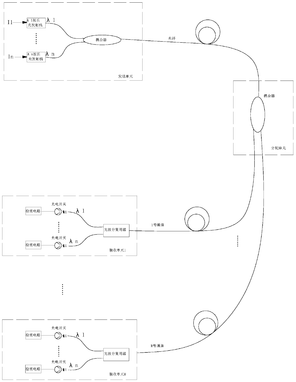
[0050] Such as figure 1 As shown, a fiber-based multi-channel switching parallel transmission system includes a sending unit, a distribution unit and M receiving units, wherein M is an integer greater than or equal to 1;

[0051] The sending unit includes n optical transmitters, and each optical transmitter corresponds to a signal source, and the n optical transmitters transmit the laser signals of different frequencies emitted by each signal source to a fiber coupler through the optical fibers connected to each other. Coupling, the signal source is a switch or a driving signal, the switch is a temperature switch, a liquid level switch or a valve position switch, etc., and the driving signal is a pump start signal, a valve opening signal or an alarm signal, etc.;

[0052]The distribution unit includes a fiber optic coupler, the fiber optic coupler in the sending unit communicates with the fiber optic coupler in the distribution unit through an optical fiber, and the distribution


PUM


Abstract

The invention discloses a multi-path switching value parallel transmission system and method based on optical fibers. The transmission system comprises a sending unit, a distribution unit and M receiving units. The transmitting unit comprises n optical transmitters, each optical transmitter corresponds to one signal source, and the n optical transmitters transmit laser signals with different frequencies, which are transmitted by each signal source, into one optical fiber coupler through optical fibers connected with the n optical transmitters for coupling; wherein the optical fiber coupler inthe sending unit is in communication connection with the optical fiber coupler in the distribution unit through an optical fiber, the distribution unit distributes laser signals to different receivingunits through the optical fiber coupler, and each receiving unit comprises the laser signals sent by each signal source; the receiving unit comprises an optical wavelength division multiplexer, and the optical wavelength division multiplexer is in communication connection with the n photoelectric switches through n optical fibers. According to the transmission system, the problems of relay fault,signal transmission interference and incapability of self-checking caused by controlling the switching value through a relay in the prior art are solved.

Description


Claims


Application Information

Patent Timeline
Owner NUCLEAR POWER INSTITUTE OF CHINA
Why Eureka
Try Eureka