Control device of natural gas ethane recovery device and using method
A recovery device and control device technology, applied in the controller, measuring device, electric controller, etc. with specific characteristics, can solve the problem that the natural gas ethane recovery device cannot operate safely and smoothly, achieve stable system pressure and avoid repeated fluctuations Effect
- Summary
- Abstract
- Description
- Claims
- Application Information
AI Technical Summary
Problems solved by technology
Method used
Image

Examples
Embodiment 1
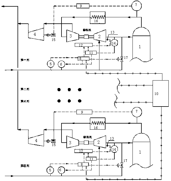
[0027] Such as figure 1 As shown, a control device for a natural gas ethane recovery device includes multiple rows of natural gas ethane recovery devices, and each row of natural gas ethane recovery devices includes a demethanizer 1, an expander expansion end 2, an expander booster end 3, The centrifugal compressor 4, the first controller 8, the second controller 9, the third controller 10, the fourth controller 11 and the expander controller 12, the expansion end 2 input end of the expander is connected with the expansion end intake pipeline, A flow detector 5 and a first pressure detector 6 are also connected to the inlet pipeline of the expansion end, the output port of the expansion end 2 of the expander is connected to the input port of the demethanizer 1 through the output pipeline of the expansion end, and the output pipeline of the expansion end is also connected with The third pressure detector 14, the output end of the demethanizer 1 is connected to the input port of th
Embodiment 2
[0036] Such as figure 1As shown, on the basis of Example 1, a branch line is connected to the input port of the demethanizer 1 on the inlet pipeline of the expansion end, and a JT valve 17 is also connected to the branch line, and the JT valve 17 and the first controller 8 electrical signal connections.
[0037] The branch line of the inlet pipeline at the expansion end is directly connected to the input port of the demethanizer 1, and the branch line is connected to the JT valve 17, which is used to transmit gas through the branch line when the expander fails. The JT valve 17 is connected to the first controller 8 for electrical signals.
[0038] It also includes a cold box 16 through which the output line of the demethanizer passes.
[0039] The natural gas ethane recovery device also includes a cold box 16, and the output pipeline of the demethanizer passes through the cold box 16 to cool down the gas in the pipeline.
[0040] The natural gas ethane recovery device has four
Embodiment 3
[0043] Such as figure 1 Shown, on the basis of embodiment 2, a kind of control device using method of natural gas ethane recovery device comprises the following steps:
[0044] In the first step, the flow detector and the first pressure detector are selected, and the first controller 8 of each column of natural gas ethane recovery device is controlled by the third controller 10, so that the first controller 8 of any three columns adopts the flow rate Detector 5 signals, and the first controller 8 of the remaining row adopts the first pressure detector 6 signals to control the speed of each row of expanders;
[0045] When the flow detector 5 is used as the feedback, the normal value of the flow is set as F0, the flow at the inlet measured by the flow detector 5 is FC, the first controller 8 adopts the classic PID algorithm, and controls the flow according to the flow deviation between FC and F0. The opening of the guide vane valve 13 is used to control the speed of the expander a
PUM
 Abstract
Description
Claims
Application Information
 - R&D Engineer
- R&D Manager
- IP Professional
- Industry Leading Data Capabilities
- Powerful AI technology
- Patent DNA Extraction
Browse by: Latest US Patents, China's latest patents, Technical Efficacy Thesaurus, Application Domain, Technology Topic.
© 2024 PatSnap. All rights reserved.Legal|Privacy policy|Modern Slavery Act Transparency Statement|Sitemap