Centrifugal compressor

A centrifugal compressor and rotor technology, which is used in mechanical equipment, machines/engines, liquid fuel engines, etc., can solve the problems of high rotational speed of centrifugal compressors, increased compressor shape and structure, and high gear noise, and achieves low noise and improved performance. The effect of energy conversion efficiency and simple shape and structure

Inactive Publication Date: 2014-11-19
NANJING JOOZ INFORMATION SCI & TECH
View PDF0 Cites 1 Cited by
  • Summary
  • Abstract
  • Description
  • Claims
  • Application Information

AI Technical Summary

Benefits of technology

This new type of machine uses two types of wheels - one with moving parts that work together like an impeller wheel for compression purposes while another part works only on its own purpose without actually making any changes or adding extra components at all. It also improves energy transfer by connecting both these movements effectively.

Problems solved by technology

This patented technical problem addressed in this patents relates to improving the efficiency and performance of an axial pump machine while reducing its size and weight without compromising their overall appearance when being applied for different types of applications like coolant systems.

Method used


Image

  • Centrifugal compressor

Examples


Embodiment Construction

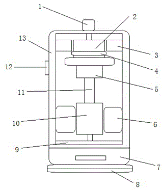
[0009] refer to figure 1 As shown, the present invention adopts the following technical scheme: a centrifugal compressor, including an air inlet 1, a movable scroll 2, a fixed scroll 3, an anti-rotation slip ring 4, a main bearing 5, a stator 6, a lower shell 7, a base 8. Separator 9, rotor 10, crankshaft 11, air outlet 12 and housing 13, the air inlet 1 is arranged on the top of the housing 13, the housing 13 is fixed on the lower shell 7, the lower shell 7 is set on the base 8, the space between the rotor 10 and the stator 6 is a sealed space, the air outlet 12 is set on the side of the housing 13, and the anti-rotation slip ring 4 is set between the movable scroll 2 and the main bearing 5 between.

[0010] The rotor 10 is connected to the main bearing 5 through the crankshaft 11, the partition plate 9 is arranged between the rotor 10 and the lower casing 7, the casing 13 and the lower casing 7 form a sealed space, and the space between the rotor 10 and the stator 6 is Th


PUM


Abstract

The invention discloses a centrifugal compressor which comprises an air suction opening, a dynamic vortex plate, a fixed vortex plate, a self-rotating-resisting sliding ring, a main bearing, a stator, a lower shell, a base, a partitioning plate, a rotor, a crankshaft, an air outlet and a shell body. The air suction opening is formed in the top of the shell body. The shell body is fixed on the lower shell which is placed on the base. A sealed space is formed between the rotor and the stator. The air outlet is formed in the side face of the shell body. The self-rotating-resisting sliding ring is placed between the dynamic vortex plate and the main bearing. The dynamic vortex plate and the fixed vortex plate are used for being connected with the rotor, so that the centrifugal compressor has the advantages of being low in noise and simple in appearance structure, and energy converting efficiency can be improved.

Description


Claims


Application Information

Patent Timeline
Owner NANJING JOOZ INFORMATION SCI & TECH
Why Eureka
Try Eureka