Hearth ash blowing method

A furnace and furnace structure technology, applied in the combustion method, combustion product treatment, removal of solid residue, etc., can solve the problems of improving heat transfer efficiency, decreasing heat transfer efficiency of the heating surface, and inability to blow the ash on the heating surface.

Inactive Publication Date: 2020-09-08
JIANGSU FRONTIER ELECTRIC TECH +1
View PDF4 Cites 1 Cited by
  • Summary
  • Abstract
  • Description
  • Claims
  • Application Information

AI Technical Summary

Benefits of technology

In this new technology, it allows users to easily see how well they have done with their boiler without having to stop working or adjust them frequently during maintenance periods. It also helps predict when there will be problems that may occur later due to changes made over time. Overall, these technical benefits make better control and efficiency in cleanliness operations while minimizing environmental impacts.

Problems solved by technology

This patented technical solution describes a method called thermal oil slip (TSO) measurement technique used by combustion engines during maintenance work. By measuring the amount of particulate emissions released into air after burning fuel, engineers are capable of accurately determining when to perform various actions such as adjustments made based upon environmental factors like NOx levels and CO2. These measurements allow us to determine which parts should have more frequent dust buildup while avoiding excessive smoke production caused by overexposure to high temperatures. Additionally, these techniques aim at providing feedback about optimal settings for sooting purposes, allowing users to make informed decisions regarding what type(of damage needs to be done before too many times due to insufficient coolant flow rates).

Method used


Image

  • Hearth ash blowing method
  • Hearth ash blowing method
  • Hearth ash blowing method

Examples


Embodiment Construction

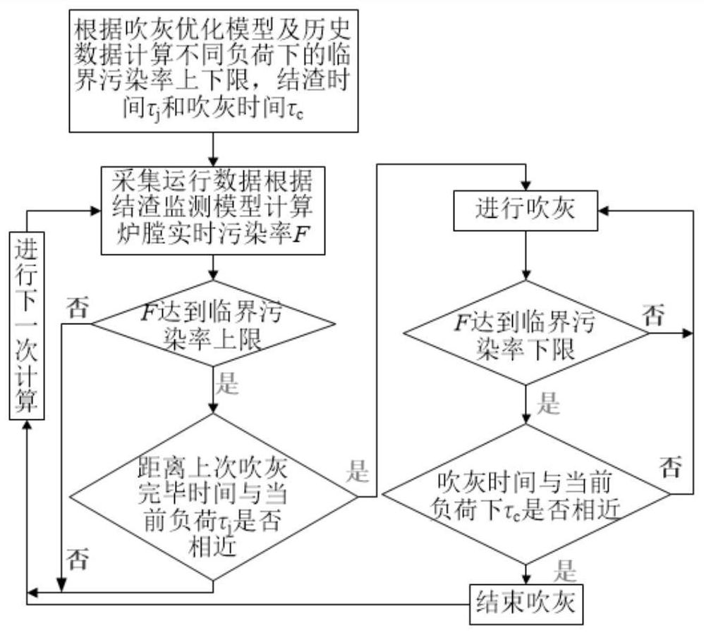
[0037] now combined with Figure 1-4 The present invention is described in further detail.

[0038] It should be noted that terms such as "upper", "lower", "left", "right", "front", and "rear" quoted in the invention are only for clarity of description, not for Limiting the practicable scope of the present invention, and the change or adjustment of the relative relationship shall also be regarded as the practicable scope of the present invention without substantive changes in the technical content.

[0039] Such as figure 1 and Figure 4 As shown, in one of the embodiments of the present invention, the selected boiler is a 600MW supercritical once-through boiler, the boiler model is HG-1956 / 25.4-YM5 type, which is an intermediate reheating, supercritical pressure variable pressure operation with built-in A once-through boiler with a recirculation pump starting system. This boiler adopts Π-shaped layout, single furnace, balanced ventilation, solid slag discharge, swirl burne


PUM


Abstract

The invention discloses a hearth ash blowing method. The hearth ash blowing method comprises the following steps that a hearth ash blowing optimization model is established; the upper limit and the lower limit of the critical pollution rate F<max>, the reasonable ash deposition time tau j and the ash blowing duration tau c are solved according to the hearth ash blowing optimization model; and start and stop of ash blowing of a hearth are controlled according to the upper limit and the lower limit of the critical pollution rate F<max>, the reasonable ash deposition time tau j and the ash blowing duration tau c. According to the hearth ash blowing method, on one hand, visual data of the real-time ash deposition condition of the hearth can be provided, effective reference is provided for ashblowing operation of the hearth, on the other hand, a ash blowing scheme is formulated by integrating the critical pollution rate and the ash blowing period, more appropriate ash blowing time and themost appropriate ash blowing duration are obtained, the heat transfer amount of the hearth based on unit time is maximized, and the operation effects of energy conservation, emission reduction and safety guarantee are achieved.

Description


Claims


Application Information

Patent Timeline
Owner JIANGSU FRONTIER ELECTRIC TECH
Why Eureka
Try Eureka