Multifunctional nursing sickbed and operation method
A multi-functional, hospital bed technology, applied in hospital beds, physiotherapy, medical science, etc., can solve the problems of high nursing intensity, difficult nursing, inconvenient turning over or massage, etc., and achieve the effect of accurate action and good effect.
- Summary
- Abstract
- Description
- Claims
- Application Information
AI Technical Summary
Problems solved by technology
Method used
Image

Examples
Example Embodiment
[0023] Example 1:
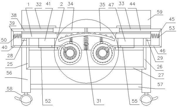
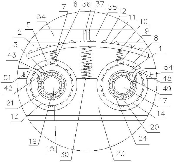
[0024] A multifunctional nursing bed, which is composed of: a bed frame 1, the inner side of the bed frame is provided with a combined bed board, the combined bed board has a massage port 2, and the massage port corresponds to a massage device, and the massage device includes a left The runner 3 and the right runner 4, the left runner is provided with a left ring 5, and a left sliding block 6 is arranged in the left ring, and the left sliding block can slide on the left ring while the left runner rotates. Free sliding inside, the left sliding block slides in the left circular ring, the left sliding block is connected to the left spring 7, the right rotating wheel has a right circular ring 8, and the right circular ring A right sliding block 9 is set inside, and the right sliding block can slide freely in the right ring when the right wheel rotates, the right sliding block slides in the right ring, and the right sliding block is connected to the right ring. Th
Example Embodiment
[0025] Example 2:
[0026] In the multifunctional nursing bed described in Embodiment 1, the left circular ring is connected to a group of left protrusions 13, the cross-sections of the left circular ring and the left sliding block are all trapezoidal sections, and the left circular The shape of the ring and the left sliding block enables the left sliding block to slide without breaking away from the left circular ring, so as to ensure coordinated action and safe use. There is a gap between the left circular ring and the left sliding block. The left protrusion pushes the left sliding block, and the left sliding block can bounce up continuously when in contact with the left protrusion; the right circular ring is connected to a group of right protrusions 14, and the right circular ring, The cross-sections of the right sliding blocks are all trapezoidal sections, and the shapes of the right circular ring and the right sliding block enable the right sliding block to slide without bre
Example Embodiment
[0027] Example 3:
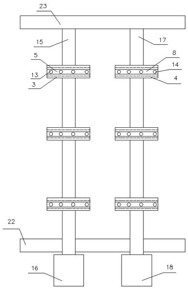
[0028] In the multifunctional nursing bed described in Embodiment 1, a set of the left rotating wheels is connected to the left rotating shaft 15, the left rotating shaft is connected to the left motor 16, and a group of the right rotating wheels is connected to the right rotating shaft 17. The right rotating shaft is connected to the right motor 18, the left rotating shaft is connected to the left bearing 19, the right rotating shaft is connected to the right bearing 20, and the left bearing is installed in the left groove 21 and fixed, which can not only provide the left rotating shaft The limit also reduces the frictional force of the left rotating shaft, and the rotation effect is good. The left groove is opened on the front support plate 22 and the rear support plate 23, and the right bearing is installed in the right groove 24 and fixed. , which can not only limit the position of the right rotating shaft but also reduce the frictional force of the right
PUM
 Abstract
Description
Claims
Application Information
 - R&D Engineer
- R&D Manager
- IP Professional
- Industry Leading Data Capabilities
- Powerful AI technology
- Patent DNA Extraction
Browse by: Latest US Patents, China's latest patents, Technical Efficacy Thesaurus, Application Domain, Technology Topic.
© 2024 PatSnap. All rights reserved.Legal|Privacy policy|Modern Slavery Act Transparency Statement|Sitemap