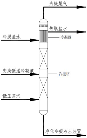
Coal chemical industry conversion low-temperature condensate steam stripping process

A technology of low-temperature condensation and coal chemical industry, which is applied in the field of coal chemical industry to transform the low-temperature condensate stripping process. It can solve problems such as blockage of stripping tower top equipment, corrosion of pipes and valves, and ammonium salt crystallization, so as to improve the average wall temperature and clean The effect of frequency reduction and thorough stripping

Active Publication Date: 2020-10-09
EAST CHINA ENG SCI & TECH
View PDF6 Cites 0 Cited by
  • Summary
  • Abstract
  • Description
  • Claims
  • Application Information

AI Technical Summary

Benefits of technology

This new technology improves the efficiency of removing nitrogen oxides (NOx) emissions from combustion engines. It uses an absorption liquid called LNG instead of regular water for this purpose. By concentrating NOx within certain parts of the system, less pollution occurs during regeneration cycles compared to conventional methods like scrubbing columns filled with lime slurry. Additionally, the use of high purity distilled waters reduces maintenance costs while maintaining good performance levels over longer periods of operation. Overall, these technical improvements result in better overall emission reduction benefits.

Problems solved by technology

This patents describes different methods used during treatments on liquids that contain nitrous oxide or sulfur compounds such as liquid hydrocarbons. These contaminants can be harmful if they come into contact with metal parts like steel pipe walls causing damage overtime. To solve this problem, these techniques involve separating them by means called scrubbers before sending it off through an industrial facility's main wastewater system.

Method used


Image

  • Coal chemical industry conversion low-temperature condensate steam stripping process

Examples


Embodiment Construction

[0024] In order to make the object, technical solution and advantages of the present invention clearer, the present invention will be further described in detail below in conjunction with the accompanying drawings and embodiments. It should be understood that the specific embodiments described here are only used to explain the present invention, not to limit the present invention.

[0025] In describing the present invention, it should be understood that the terms "length", "width", "upper", "lower", "front", "rear", "left", "right", "vertical", The orientation or positional relationship indicated by "horizontal", "top", "bottom", "inner", "outer", etc. are based on the orientation or positional relationship shown in the drawings, and are only for the convenience of describing the present invention and simplifying the description, rather than Nothing indicating or implying that a referenced device or element must have a particular orientation, be constructed, and operate in a par


PUM


Abstract

The invention discloses a coal chemical industry conversion low-temperature condensate steam stripping process which comprises the following steps: S1, acquiring low-temperature conversion condensateseparated by a conversion separator, and preheating the conversion condensate; S2, introducing the preheated conversion condensate into a stripping tower from the middle part, and introducing low-pressure steam into the stripping tower from the bottom; S3, carrying out reverse contact stripping on the conversion condensate and low-pressure steam in a filler or tower tray of a stripping section, carrying out reverse contact stripping on stripping gas after stripping and a tower top condensate reflux in a filler or tower tray of a rectifying section, and rectifying the reflux; S4, condensing therectified stripping gas through a tower top condenser, sending the condensed and separated stripping gas to a downstream device, and enabling the separated reflux liquid to flow back to the rectifying section; by changing the feeding position of the low-temperature condensate, changing a cooling medium of a tower top heat exchanger and optimizing the operating temperature of the heat exchanger. Therefore, problems of corrosion of thetower top condenser, pipelines and valves and ammonium salt crystallization of a lower area of the tower top condenser and a gas-phase pipeline of an acid water vapor extraction opening can be effectively solved.

Description


Claims


Application Information

Patent Timeline
Owner EAST CHINA ENG SCI & TECH
Why Eureka
Try Eureka