Deicing device for power cable
A technology for power cables and power chambers, which is applied in the field of deicing devices for power cables, can solve problems such as difficult maintenance of power cables, abnormal lines, etc., and achieve the effects of good snow removal effect, simple structure, and good application prospects
- Summary
- Abstract
- Description
- Claims
- Application Information
AI Technical Summary
Benefits of technology
Problems solved by technology
Method used
Image

Examples
Embodiment 1
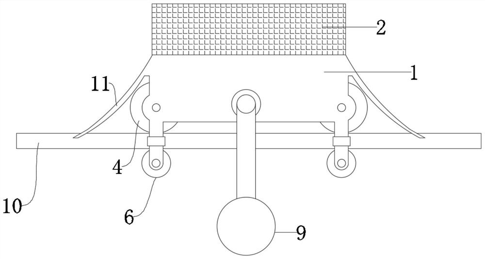
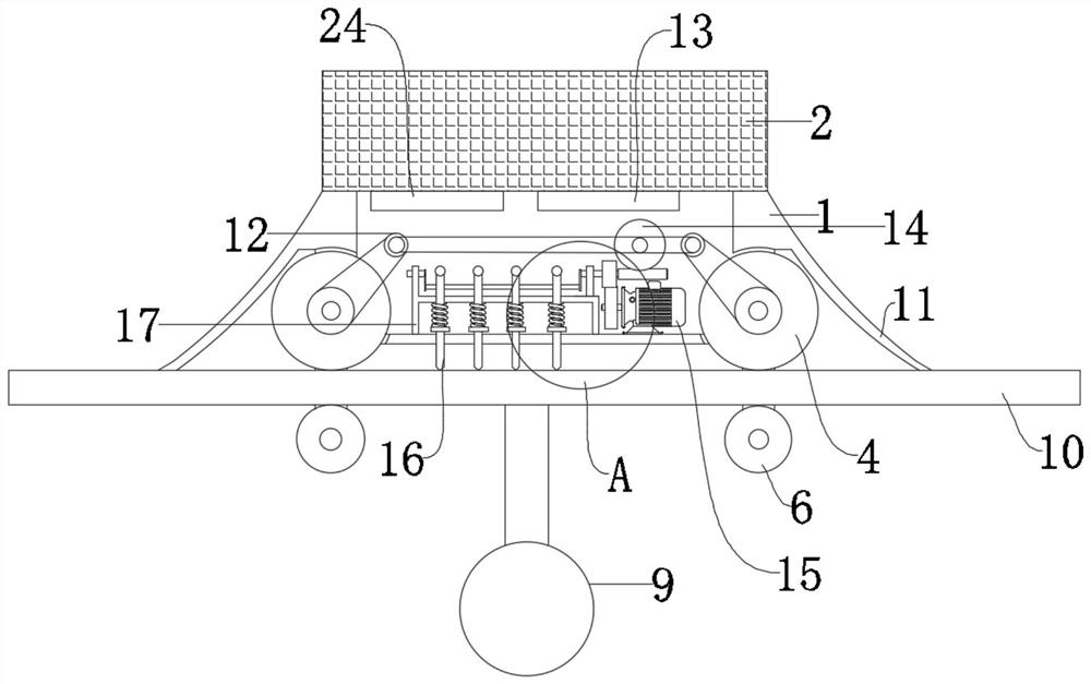
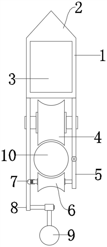
[0024] see Figure 1-5 , a deicing device for a power cable 10, comprising a box body 1, and rollers 4 are installed in rotation at both ends of the box body 1, and the end faces of the rollers 4 are concavely arranged; and then can be effectively clamped on the cable 10; the box body 1 is provided with a power chamber 3, and the power chamber 3 is provided with a driving assembly and a deicing assembly, and the driving assembly includes a motor 15, a mounting frame 17, a rotating shaft 21 and a driving rod 19, The motor 15 is fixedly mounted on the bottom of the power chamber 3, the mounting frame 17 is fixedly arranged on the side of the motor 15, and the rotating shaft 21 is rotatably mounted on the mounting frame 17 and connected with the rotating shaft of the motor 15 through a gear pair , and then realize the rotation under the action of the motor 15, the eccentric connection between the drive rod 19 and the rotating shaft 21 further acts on the deicing assembly; the deicin
Embodiment 2
[0033]This embodiment has made the following improvements on the basis of Embodiment 1, wherein it includes a box body 1, and rollers 4 are installed in rotation at both ends of the box body 1, and the end faces of the rollers 4 are concavely arranged; thus, it can effectively It is clamped on the cable 10; a power chamber 3 is opened in the box body 1, and a driving assembly and a deicing assembly are arranged in the power chamber 3, and the driving assembly includes a motor 15, a mounting frame 17, and a rotating shaft 21 and the drive rod 19, the motor 15 is fixedly mounted on the bottom of the power chamber 3, the mounting frame 17 is fixedly arranged on the side of the motor 15, and the rotating shaft 21 is mounted on the mounting frame 17 in rotation and between the rotating shaft of the motor 15 They are connected through a gear pair, and then rotate under the action of the motor 15. The eccentric connection between the drive rod 19 and the rotating shaft 21 further acts on
PUM
 Abstract
Description
Claims
Application Information
 - R&D Engineer
- R&D Manager
- IP Professional
- Industry Leading Data Capabilities
- Powerful AI technology
- Patent DNA Extraction
Browse by: Latest US Patents, China's latest patents, Technical Efficacy Thesaurus, Application Domain, Technology Topic.
© 2024 PatSnap. All rights reserved.Legal|Privacy policy|Modern Slavery Act Transparency Statement|Sitemap