Small and micro station site selection method and device and electronic equipment

A micro-station and micro-particle technology, applied in the field of communication, can solve the problems such as the great difference between the optimal site site, the inability to simulate, and the inability to realize the site selection of the base station, so as to save the cost of manual addressing and avoid the waste of inaccurate resources

Active Publication Date: 2021-01-19
CHINA MOBILE GROUP ZHEJIANG +1
View PDF5 Cites 0 Cited by
  • Summary
  • Abstract
  • Description
  • Claims
  • Application Information

AI Technical Summary

Benefits of technology

The technology described by this inventor allows for quicker identification of tiny stations at different locations within an urban environment without having them manually marked up or moved around during construction phases. This helps reduce costs associated with manual inspections while still providing accurate results compared to simulations.

Problems solved by technology

This patents discusses two technical challenges: one being related to increasing cellular bandwidth usage while also ensuring good reception on critical devices like mobile phone calls or video streaming due to increased demand over limited connections during peak hours. Secondly, there may be situations where it becomes difficult if only few pico/malls have been deployed without causing congestion issues. These factors make finding suitable sites very complicated because existing solutions require significant human effort and materials resource allocation.

Method used


Image

  • Small and micro station site selection method and device and electronic equipment
  • Small and micro station site selection method and device and electronic equipment
  • Small and micro station site selection method and device and electronic equipment

Examples


Embodiment Construction

[0026] Exemplary embodiments of the present invention will be described in more detail below with reference to the accompanying drawings. Although exemplary embodiments of the present invention are shown in the drawings, it should be understood that the invention may be embodied in various forms and should not be limited to the embodiments set forth herein. Rather, these embodiments are provided for more thorough understanding of the present invention and to fully convey the scope of the present invention to those skilled in the art.

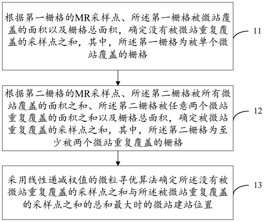
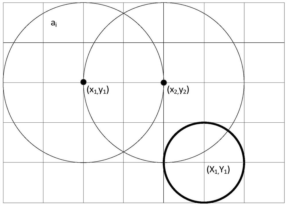
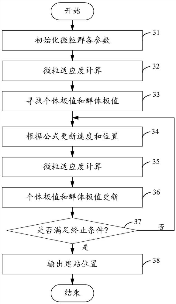
[0027]The measurement report (Measurement Report, MR) sampling point can indicate the amount of traffic to a certain extent. The embodiment of the present invention provides a small and micro station site selection method, according to the MR positioning grid distribution of sampling points and the construction of small and micro stations In principle, based on the improved Particle Swarm Optimization (PSO) of Linearly Decreasing Weight (LDW), the


PUM


Abstract

An embodiment of the invention relates to the technical field of communication, and discloses a small and micro station site selection method and device and electronic equipment. The method comprisesthe steps of determining the sum of sampling points which are not repeatedly covered by a micro station according to MR sampling points of a first grid, the area, covered by the micro station, of thefirst grid and the total area of the grids; determining the sum of the sampling points repeatedly covered by the micro stations according to the MR sampling points of the second grid, the sum of the areas, repeatedly covered by all the micro stations, of the second grid, the sum of the areas, repeatedly covered by any two micro stations, of the second grid and the total area of the grids; determining a micro-station building position when the sum of the sampling points which are not repeatedly covered by the micro-station and the sum of the sampling points which are repeatedly covered by the micro-station are maximum by adopting a particle optimization algorithm of a linear decreasing weight. By means of the mode, the small micro-station site can be accurately and rapidly found, and the small micro-stations can be accurately released to the coverage hot spot area.

Description


Claims


Application Information

Patent Timeline
Owner CHINA MOBILE GROUP ZHEJIANG
Why Eureka
Try Eureka