Sampling equipment for detecting atmospheric pollution

The technology of sampling equipment and air outlet pipe is applied in the field of sampling equipment for detecting atmospheric pollution, which can solve the problems of difficult atmosphere, full contact of culture liquid, poor sealing performance of atmospheric sampling device, etc., and achieves the effect of easy disassembly and cleaning

Pending Publication Date: 2021-02-19
XIAN SENWAS AGRI SCI & TECH
View PDF0 Cites 0 Cited by
  • Summary
  • Abstract
  • Description
  • Claims
  • Application Information

AI Technical Summary

Benefits of technology

This new design allows for easy maintenance without having to shut off any equipment or process altogether during replacement. It also includes features like folding an envelope that holds both components together when they're stored inside it, inserting a plug-in mechanism between two parts called the pump body, attaching a threaded connection on one part by means of bolts, turning a locknut tightened, pushing another component onto top of the other before closing them up again.

Problems solved by technology

This patented describes different ways to measure harmful gases from indoor environments such as building ventilation systems. However, current devices are poorly sealed due to their lack of proper design features preventing adequate exposure during sample collection procedures. Additionally, there may also exist issues related to maintaining sterility between the collector's chamber and its surrounding environment after being opened up by workers at work hours.

Method used


Image

  • Sampling equipment for detecting atmospheric pollution
  • Sampling equipment for detecting atmospheric pollution
  • Sampling equipment for detecting atmospheric pollution

Examples


Embodiment Construction

[0018] The following will clearly and completely describe the technical solutions in the embodiments of the present invention with reference to the accompanying drawings in the embodiments of the present invention. Obviously, the described embodiments are only some, not all, embodiments of the present invention. Based on the embodiments of the present invention, all other embodiments obtained by persons of ordinary skill in the art without making creative efforts belong to the protection scope of the present invention.

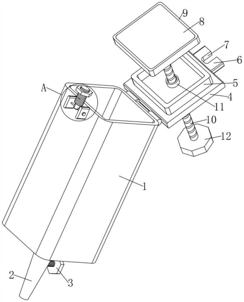
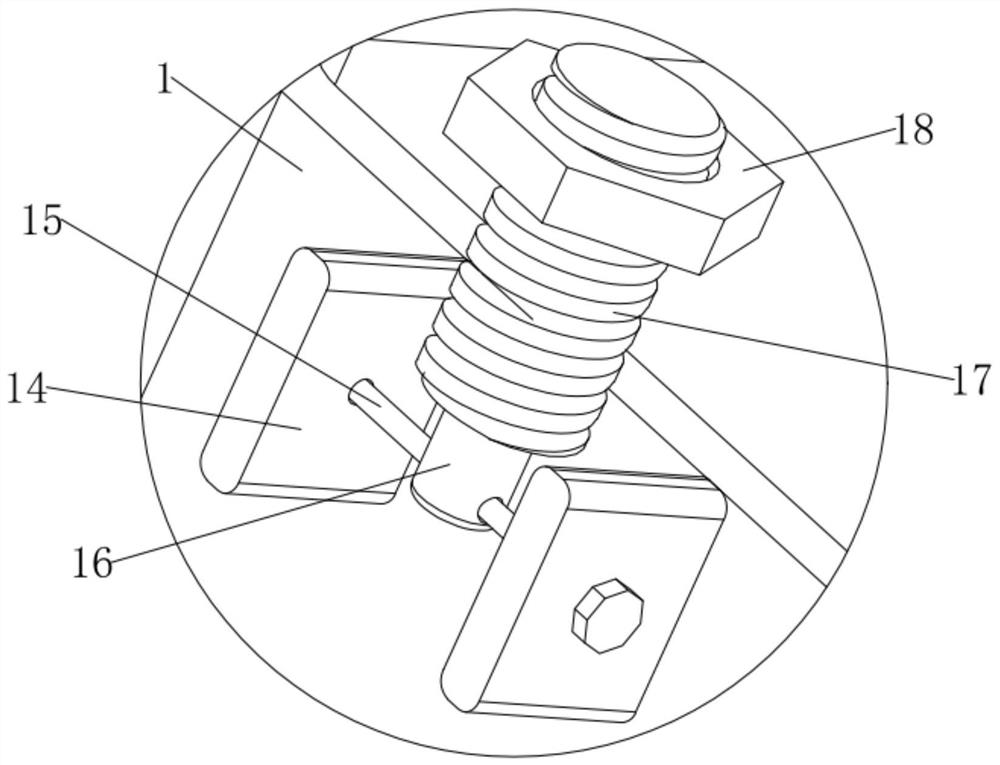
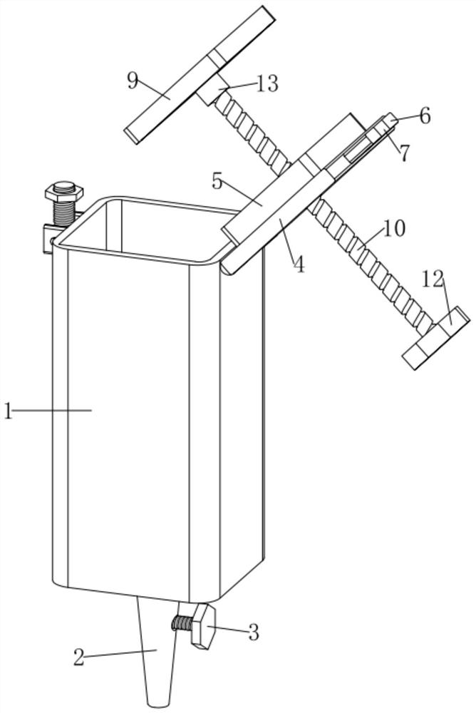
[0019] see Figure 1-Figure 3 , the present invention provides a sampling device for detecting air pollution, comprising a storage cylinder 1, the lower end of the storage cylinder 1 is fixedly connected with an air outlet pipe 2, the right part of the air outlet pipe 2 is equipped with a valve 3, and the upper right part of the storage cylinder 1 passes through a closed A sealing cover 4 is hinged movable, the upper end of the sealing cover 4 is dug with a round


PUM


Abstract

The invention discloses sampling equipment for detecting atmospheric pollution, and the equipment comprises a storage cylinder; the lower end of the storage cylinder is fixedly connected with an air outlet pipe, the right portion of the air outlet pipe is provided with a valve, the right portion of the upper end of the storage cylinder is movably hinged to a sealing cover through a hinge, a roundhole is dug in the upper end of the sealing cover, and the upper end of the storage cylinder is fixedly connected with a threaded ring; a first lead screw is in threaded connection in the threaded ring and the round hole, the upper end of the first lead screw is rotationally connected with a push plate through a limiting ring, the push plate is matched with the storage barrel, the sealing cover isturned over, the push plate is inserted into the storage barrel, the second lead screw is clamped in the clamping hole, the locking nut is rotated to press the first fixed plate, and the position ofthe first fixed plate is fixed, thereby achieving the fixing of the positions of the sealing cover and the storage cylinder; the valve is opened, the first lead screw is rotated, the rotation of the first lead screw drives the push plate to move downwards, and the push plate extrudes the atmosphere collected in the storage cylinder out of the air outlet pipe.

Description


Claims


Application Information

Patent Timeline
Owner XIAN SENWAS AGRI SCI & TECH
Why Eureka
Try Eureka