Movable grouting equipment

A mobile, grouting technology, applied in mining equipment, shaft equipment, clay preparation devices, etc., can solve the problems of inability to realize automatic pulping and precise grouting, poor construction environment, and large space, and achieve the Grout and grouting intelligent control, improve pulping and grouting efficiency, solve the effect of grouting equipment dispersion

Pending Publication Date: 2021-03-05
JIANGSU XCMG CONSTR MASCH RES INST LTD
View PDF0 Cites 1 Cited by
  • Summary
  • Abstract
  • Description
  • Claims
  • Application Information

AI Technical Summary

Benefits of technology

This technology uses two smaller mobile devices instead of just one device for better dispensation or accuracy during paper making processes like punches and scrapers. It also helps improve upon existing methods such as manual operation with carts and machines without causing issues related to dispersal, movement, and accurate placement of materials within the process itself.

Problems solved by technology

This patented technical problem addressed in this patents relates to improving the accuracy and efficiency of building materials during manufacturing processes like concrete casting or tunneling roadway repair. Ground-reinforce cement (GRC) material can cause issues with cracking due to changes over time caused by external factors including temperature variations, moisture content differences between different parts of the GRC product, and other environmental conditions that may affect its performance. Current methods involve manual laborers adjusting various aspects of the process based upon their own judgment without realistically accounting for these variables.

Method used


Image

  • Movable grouting equipment
  • Movable grouting equipment
  • Movable grouting equipment

Examples


Embodiment Construction

[0031] The present invention will be further described below in conjunction with the accompanying drawings. The following examples are only used to illustrate the technical solution of the present invention more clearly, but not to limit the protection scope of the present invention.

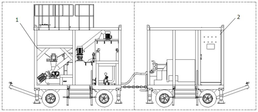
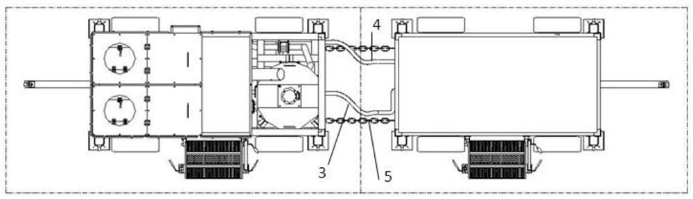
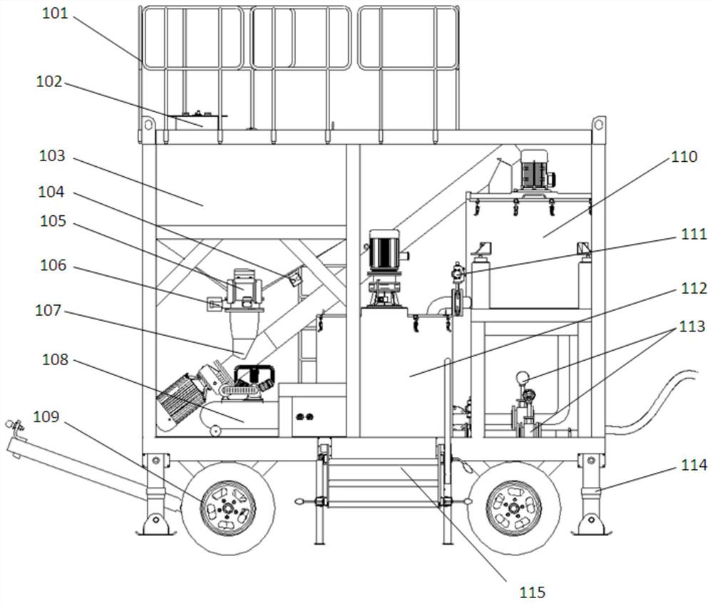
[0032] A kind of movable grouting equipment of the present invention, the structure sees Figure 1-Figure 4 As shown, it includes a pulping unit 1 and a grouting control unit 2; the pulping unit 1 and the grouting control unit 2 can be detachably arranged on a driving car, and the driving car can drive the pulping unit 1 and the grouting The control unit 2 moves. The driving vehicle can adopt the wheeled trailer or the crawler chassis running mechanism in the prior art, and the slurry making unit 1 and the grouting control unit 2 can be arranged on one driving vehicle, or can be respectively arranged on two driving vehicles, two The detachable connection between the driving carts. see figure 1


PUM


Abstract

The invention discloses movable grouting equipment. The movable grouting equipment comprises a grout making unit and a grouting control unit; the grout making unit is used for making cement into cement grout, and the grouting control unit is used for injecting the cement grout into grouting holes to complete grouting; and the grout making unit and the grouting control unit are detachably mounted on a driving vehicle. According to the movable grouting equipment, the integrated movable grout making unit and the integrated movable grouting control unit are adopted, so that convenience and quickness in movement are realized.

Description


Claims


Application Information

Patent Timeline
Owner JIANGSU XCMG CONSTR MASCH RES INST LTD
Why Eureka
Try Eureka