Microelectronic efficient heat dissipation device

A heat dissipation device and microelectronics technology, applied in cooling/ventilation/heating transformation, modification through conduction heat transfer, modification using liquid cooling, etc., can solve the problem of large space for heat dissipation devices, accelerated chip loss, and thermal function decline, etc. problems, to prevent dust from contacting with silica gel, prolong service life and reduce volume

Active Publication Date: 2021-03-19
INNER MONGOLIA UNIV OF TECH
View PDF14 Cites 2 Cited by
  • Summary
  • Abstract
  • Description
  • Claims
  • Application Information

AI Technical Summary

Benefits of technology

This patented technology provides an efficient way to remove excessive thermal energy generated during electronic devices' operation without causing damage or reducing their performance level significantly. By connecting this system between two components called chips (a small part) on top of each other, it allows fluid communication within them when there are changes happening over time. Additionally, the use of special materials like silver gels helps keep particles separated even if they come close enough together. Overall, these technical features improve efficiency and durability of electronic equipment systems.

Problems solved by technology

The technical problem addressed in this patented text relates how to improve thermal management during use of computer systems with high power density components such as CPUs (central processing units) due to their increasing operating frequency. This issue arises where excessive heat generated within these devices causes damage or reduces its performance overtime. To solve this problem, various techniques have been developed for improving heat removal efficiency without adding extra weight or making cleanup difficult.

Method used


Image

  • Microelectronic efficient heat dissipation device
  • Microelectronic efficient heat dissipation device
  • Microelectronic efficient heat dissipation device

Examples


Embodiment Construction

[0022] A specific embodiment of the present invention will be described in detail below in conjunction with the accompanying drawings, but it should be understood that the protection scope of the present invention is not limited by the specific embodiment.

[0023] In this application document, unspecified component models and structures are all prior art known to those skilled in the art, and those skilled in the art can set them according to the needs of the actual situation. In the embodiments of this application document No specific restrictions are made.

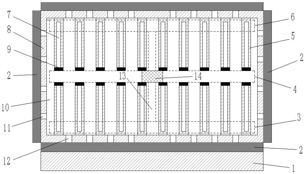
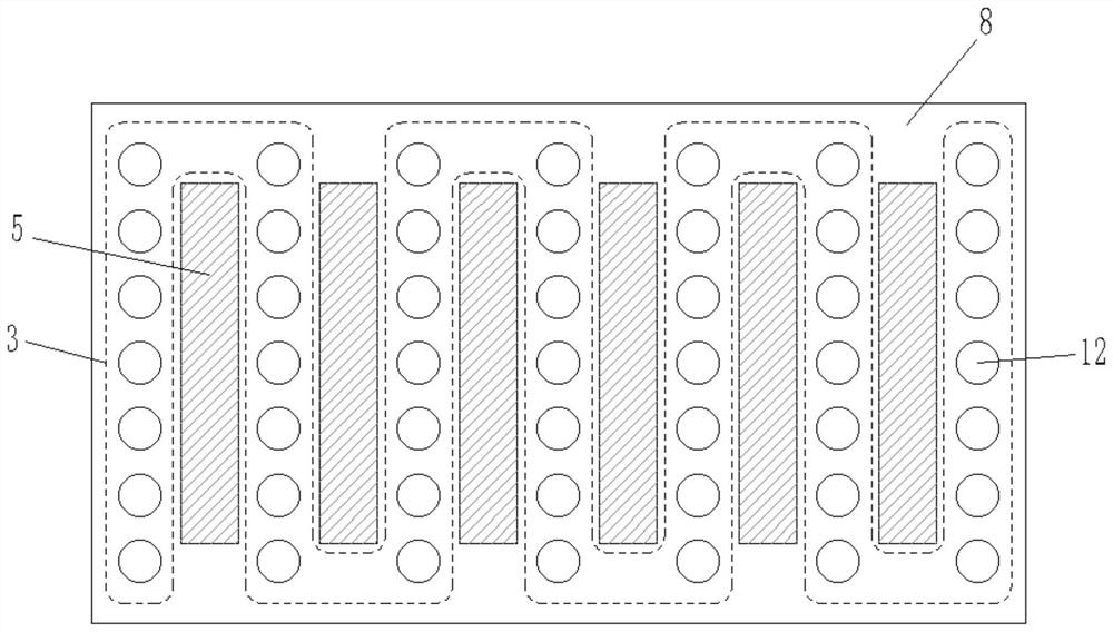
[0024] Specifically, such as Figure 1-3 As shown, the embodiment of the present invention provides a high-efficiency heat dissipation device for microelectronics, including a heat dissipation plate 8, the heat dissipation plate 8 is adhered to the heating surface of the chip 1 through silica gel 2, the heat dissipation plate 8 is a hollow structure, and the heat dissipation plate The inner cavity 10 of 8 is provided with


PUM


Abstract

The invention discloses a microelectronic efficient heat dissipation device. The device comprises a heat dissipation plate, wherein the heat dissipation plate is adhered to a heating surface of a chipthrough silica gel, the heat dissipation plate is of a hollow structure, and a circulating pump is arranged in an inner cavity of the heat dissipation plate; a first cooling liquid circulation channel which is arranged on the lower wall of the inner cavity; a second cooling liquid circulation channel which is arranged on the upper wall of the inner cavity; a third cooling liquid circulation channel which is arranged between the first cooling liquid circulation channel and the second cooling liquid circulation channel, and the third cooling liquid circulation channel is respectively communicated with the first cooling liquid circulation channel and the second cooling liquid circulation channel through a cooling liquid communication channel; a powder releaser which is arranged in the circulating pump; and a first temperature sensor which is arranged in the circulating pump. By using the device, the volume occupied by the heat dissipation device can be effectively reduced, the heat dissipation plate is comprehensively attached to the heating surface of the chip, and dust can be effectively prevented from making contact with silica gel.

Description


Claims


Application Information

Patent Timeline
Owner INNER MONGOLIA UNIV OF TECH
Why Eureka
Try Eureka