Robot cleaning path planning method and device and floor washing robot
A path planning and robot technology, which is applied in the direction of instruments, motor vehicles, transportation and packaging, etc., can solve the problems such as water leakage and missing sweeping of floor washing robots, and achieve good cleaning effect and avoid water leakage and missing sweeping effect
- Summary
- Abstract
- Description
- Claims
- Application Information
AI Technical Summary
Problems solved by technology
Method used
Image


Examples
Example Embodiment
[0033]Example one
[0034]In some optional embodiments, please refer tofigure 2 ,figure 2 It is a flow chart of an embodiment of a robot cleaning path planning method.
[0035]Such asfigure 2 As shown, the first aspect of this application provides a robot cleaning path planning method, and the method includes the following steps:
[0036]S1100, obtains area size information of the area to be cleaned;
[0037]At the time of implementation, the washing robot is provided with a laser radar or a camera that scans the cleaning area by laser radar or the camera to obtain area size information of the area to be cleaned, including but not limited to the length, width of the zone to be cleaned. Regional shape and other information.
[0038]S1200, according to the length of the area size information and the preset path, divide the rectangular area to be cleaned into a plurality of overlapping regions;
[0039]The path superposition length is a constant that is pre-set in advance. In some embodiments, the path su
Example Embodiment
[0052]Example 2
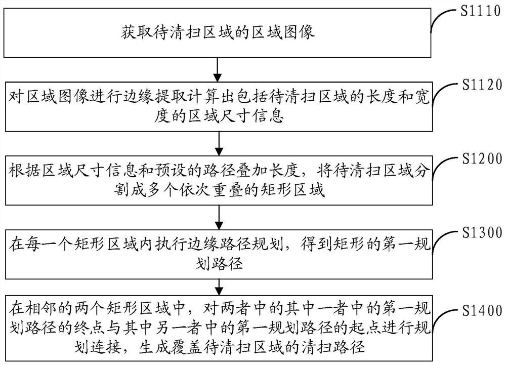
[0053]In some optional embodiments, seeimage 3 ,image 3 It is a flowchart of the present application to calculate the length and width of the region to be cleaned.
[0054]Such asimage 3 As shown, the step of obtaining the area size information of the area to be cleaned is included in the following steps:
[0055]S1110, acquire an area image to be cleaned;
[0056]S1120, the edge extraction of the region image calculates an area size information including the length and width of the width to be cleaned.
[0057]At the time of implementation, the scrubber is provided with a camera or camera that collects an image to be cleaned by the camera or the camera, and then detects the image, such as the edge detection of the image, the Sobel operator edge detection, etc., and the edge detection is a graphic image. Processing, computer vision, and machine vision, is usually used for feature extraction and feature detection, intended to detect a significantly changed edge or discontinuous regi
Example Embodiment
[0058]Example three
[0059]In some optional embodiments, seeFigure 4 ,Figure 4 It is a flowchart of the first planning path for one embodiment of the present application.
[0060]Such asFigure 4 As shown, the edge path planning is performed in each rectangular area, and the step of obtaining a first planning path of the rectangle includes the steps of:
[0061]S1310, with a corner of the rectangular region, generate a first edge path equal to the first side edge length along the first side edge plan of the rectangular region;
[0062]S1320, with the starting point of the first edge path, the second edge path equal to the second side edge length is generated along the second side edge plan of the area to be cleaned;
[0063]S1330, the end point of the second edge path is starting, and the third edge path such as long and direction in the direction of the first edge path is generated along the third side edge of the rectangular region;
[0064]S1340, the end point of the third edge path is the starting
PUM
 Abstract
Description
Claims
Application Information
 - R&D Engineer
- R&D Manager
- IP Professional
- Industry Leading Data Capabilities
- Powerful AI technology
- Patent DNA Extraction
Browse by: Latest US Patents, China's latest patents, Technical Efficacy Thesaurus, Application Domain, Technology Topic.
© 2024 PatSnap. All rights reserved.Legal|Privacy policy|Modern Slavery Act Transparency Statement|Sitemap